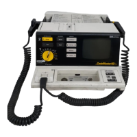
Monitoring
Using Leads to Monitor
3-3
5-Wire Patient Cable
Table 3-4, “5-Wire Electrode Placement,” on page 3-3 describes a typical lead-wire
placement using the 5-wire patient cable. Table 3-5, “Lead Configurations,” on page
3-3 shows how the individual leads are formed using the individual leadwires.
Table 3-3 Lead Formation
Lead + — ref
I LA RA LL
II LL RA LA
III LL LA RA
Table 3-4 5-Wire Electrode Placement
Electrode Placement
RA/White Near right midclavicular line, directly below clavicle.
LA/Black Near left midclavicular line, directly below clavicle.
LL/Red Below the left pectoral muscle on the left midclavicular line.
RL/Green Below the right pectoral muscle on the right midclavicular line.
V/Brown As appropriate for the V lead to be monitored (V1 - V6).
Table 3-5 Lead Configurations
Lead Leadwire Combinations
I LA - RA
II LL - RA
III LL - LA
aVR RA - .5 (LA + LL)
aVF LL - .5 (RA + LA)