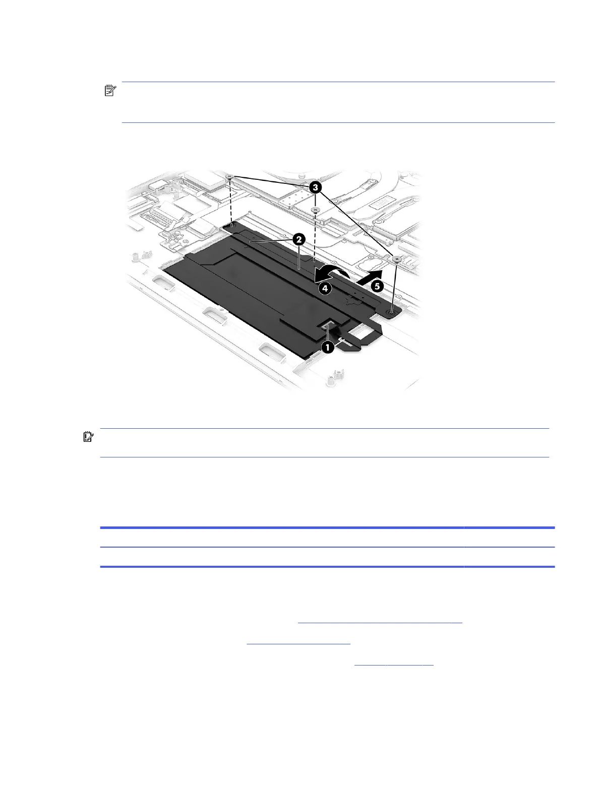
3. Remove the three Phillips M2.0 × 2.0 screws (3) that secure the touchpad to the computer.
NOTE: To avoid damaging the display, lift the computer o the display before removing the touchpad.
Because you have to rotate the top of the touchpad up at an angle during removal, the bottom can pivot
down and damage the display if the touchpad is sitting directly on top of the display.
4. Rotate the touchpad upward to a 20° to 30° angle (4), and then pull the touchpad into the computer at an
angle to remove it (5).
To install the touchpad, reverse this procedure.
IMPORTANT: To avoid damaging the display during touchpad installation, before inserting the touchpad
into the computer, lift the computer up o the display.
Heat sink
To remove the heat sink, use this procedure and illustration.
Table 5-11
Heat sink description and part number
Description Spare part number
Heat sink N22936-001
Before removing the heat sink, follow these steps:
1. Prepare the computer for disassembly (see Preparation for disassembly on page 33).
2. Remove the bottom cover (see Bottom cover on page 33).
3. Disconnect the battery cable from the system board (see Battery on page 42).
Remove the heat sink:
1. Disconnect the two fan cables from the system board (1).
Heat sink
47