Controller enclosure—rear panel layout 15
NOTE: MSA 2040 controller enclosures support hot-plug replacement of redundant controller modules,
fans, power supplies, and I/O modules. Hot-add of drive enclosures is also supported.
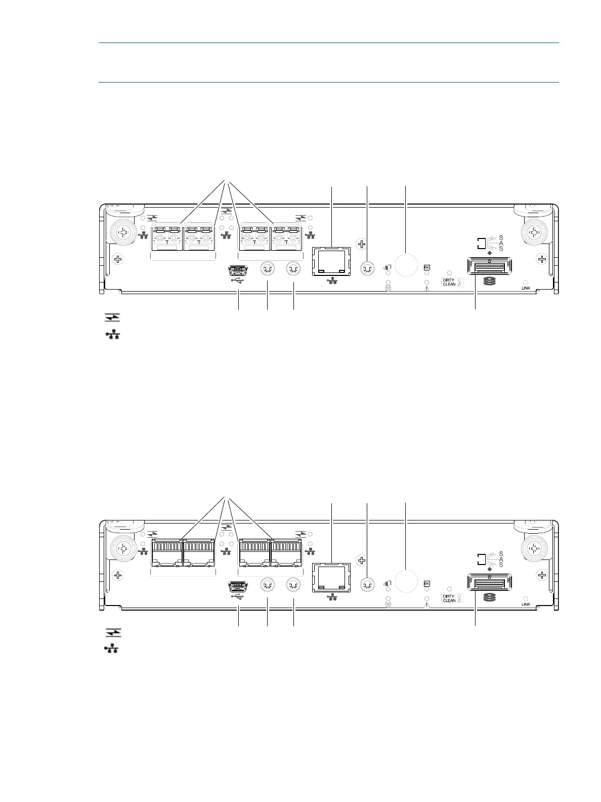
MSA 2040 SAN controller module—rear panel components
Figure 4 shows host ports configured with either 8/16 Gb FC or 10GbE iSCSI SFPs. The SFPs look
identical.
Refer to the LEDs that apply to the specific configuration of your Converged Network Controller ports.
Figure 4 MSA 2040 SAN controller module face plate (FC or 10GbE iSCSI)
Figure 5 shows Converged Network Controller ports configured with 1 Gb RJ-45 SFPs.
Figure 5 MSA 2040 SAN controller module face plate (1 Gb RJ-45)
1 Host ports: used for host connection or replication
[see "Install an SFP transceiver" (page 95)]
2 CLI port (USB - Type B)
3 Service port 2 (used by service personnel only)
4 Reserved for future use
5 Network port
6 Service port 1 (used by service personnel only)
7 Disabled button (used by engineering only)
(Sticker shown covering the opening)
8 SAS expansion port
CACHE
CLI
CLI
LINK
ACT
6Gb/s
SERVICE−1SERVICE−2
PORT 1 PORT 2 PORT 3 PORT 4
157
3 4
6
8
2
= FC LEDs
= 10GbE iSCSI LEDs
CACHE
CLI
CLI
LINK
ACT
6Gb/s
SERVICE−1SERVICE−2
PORT 1 PORT 2 PORT 3 PORT 4
= 1 Gb iSCSI LEDs (all host ports use 1 Gb RJ-45 SFPs in this figure)
157
3 4
6
8
2
= FC LEDs