22 Installing the enclosures
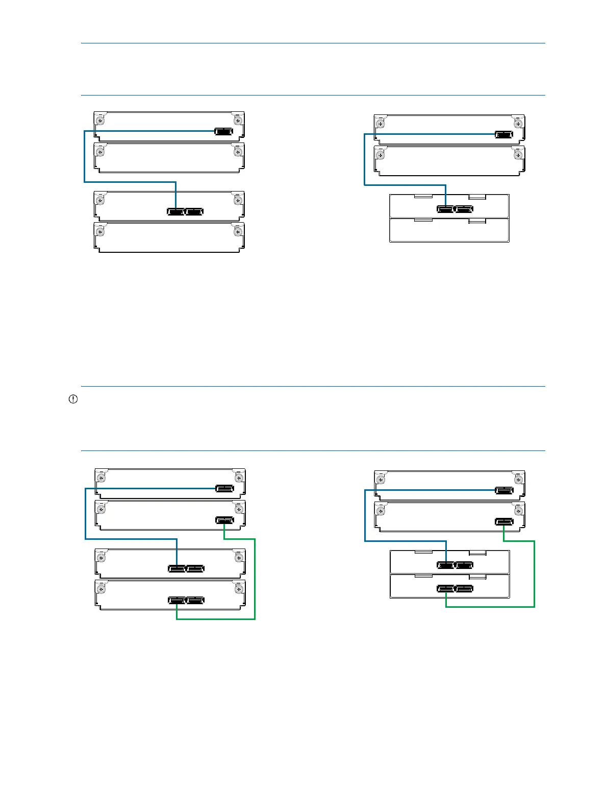
NOTE: For clarity, the schematic illustrations of controller and expansion modules shown in this section
provide only relevant details such as expansion ports within the module face plate outline. For detailed
illustrations showing all components, see "Controller enclosure—rear panel layout" (page 14).
Figure 9 Cabling connections between the MSA 2040 controller and a single drive enclosure
The figure above shows examples of the MSA 2040 controller enclosure—equipped with a single
controller module—cabled to a single drive enclosure equipped with a single expansion module. The
empty I/O module slot in each of the enclosures is covered with an IOM blank to ensure sufficient air flow
during enclosure operation. The remaining illustrations in the section feature enclosures equipped with dual
IOMs.
IMPORTANT: If the MSA 2040 controller enclosure is configured with a single controller module, the
controller module must be installed in the upper slot, and an I/O module blank must be installed in the
lower slot (shown above). This configuration is required to allow sufficient air flow through the enclosure
during operation.
Figure 10 Cabling connections between the MSA 2040 controller and a single drive enclosure
In Out
1B
1A
2A
2B
Controller A
IOM blank
P1 P2
Controller A
IOM blank
= LFF 12-drive enclosure
= SFF 25-drive enclosure
21
1
2
IOM blank
IOM blank
1B
1A
2A
2B
In Out
1B
1A
2A
2B
Controller A
Controller B
In Out
P1 P2
Controller A
Controller B
P1 P2
= LFF 12-drive enclosure
= SFF 25-drive enclosure
21
1
2
1B
1A
2A
2B