Connecting controller and drive enclosures 23
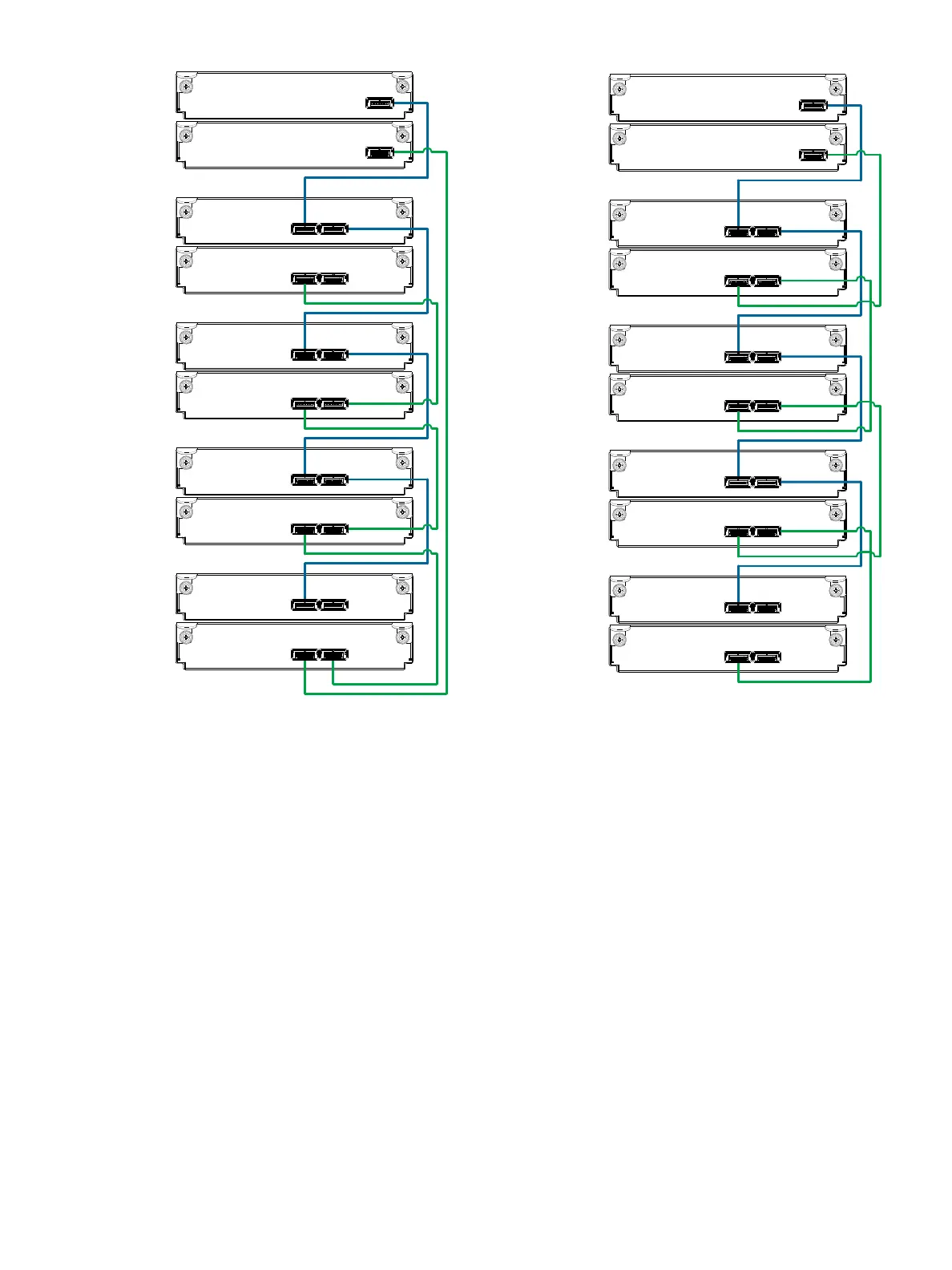
Figure 11 Cabling connections between MSA 2040 controllers and LFF drive enclosures
The diagram at left (above) shows fault-tolerant cabling of a dual-controller enclosure cabled to MSA 2040
6 Gb 3.5" 12-drive enclosures featuring dual-expansion modules. Controller module 1A is connected to
expansion module 2A, with a chain of connections cascading down (blue). Controller module 1B is
connected to the lower expansion module (5B), of the last drive enclosure, with connections moving in the
opposite direction (green). Fault-tolerant cabling allows any drive enclosure to fail—or be removed—while
maintaining access to other enclosures.
The diagram at right (above) shows the same storage components connected using straight-through
cabling. Using this method, if a drive enclosures fails, the enclosures that follow the failed enclosure in the
chain are no longer accessible until the failed enclosure is repaired or replaced.
Controller A
Controller B
1A
1B
In
Out
2A
2B
3A
3B
4A
4B
5A
5B
In
Out
In
Out
In
Out
In
Out
In
Out
In
Out
Out
In
Fault-tolerant cabling
Controller A
Controller B
1A
1B
In
Out
2A
2B
3A
3B
4A
4B
5A
5B
In
Out
In
Out
In
Out
In
Out
In
Out
In
Out
Out
In
Straight-through cabling