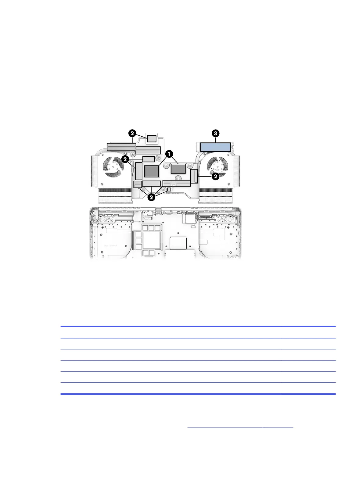
To apply the grease at the proper 0.3 mm thickness:
a. Fold a standard A4 sheet of paper into fourths.
b. Create a grease containing area by cutting a rectangular hole in the folded paper deck that is
the same size as the processor and graphics chip die surfaces.
c. Align the hole to the processor or graphics die surfaces, and while holding the paper deck still,
squeeze the thermal grease out of the syringe into the containing area.
d. Scrape the excess grease flat with a ruler or a plastic card to spread it out and fill the
containment area evenly.
To install the heat sink/fan assembly, reverse this procedure.
Solid-state drive, primary, models with 5070Ti, 5080, or 5090 graphics
To remove the primary solid-state drive (SSD), use this procedure and illustration. The primary SSD is
located under the heat sink on models with 5070Ti, 5080, or 5090 graphics.
Table 7-5
SSD descriptions and part numbers
Description Spare part number
2 TB, TLC, PCIe-4 × 4 N77396-005
1 TB, TLC, PCIe-5 × 4 P32587-005
1 TB, TLC, PCIe-4 × 4 N77395-005
1 TB, PCIe-4 × 4 N77394-005
512 GB, PCIe-4 × 4 N77392-005
Before removing the primary SSD, follow these steps:
1. Prepare the computer for disassembly (see Preparation for disassembly on page 38).
Solid-state drive, primary, models with 5070Ti, 5080, or 5090 graphics
57