Removal and Replacement Procedures
Maintenance and Service Guide 5–37
Ä
CAUTION: Support the display assembly when removing the following
screws. Failure to support the display assembly can result in damage to
the display assembly and other computer components.
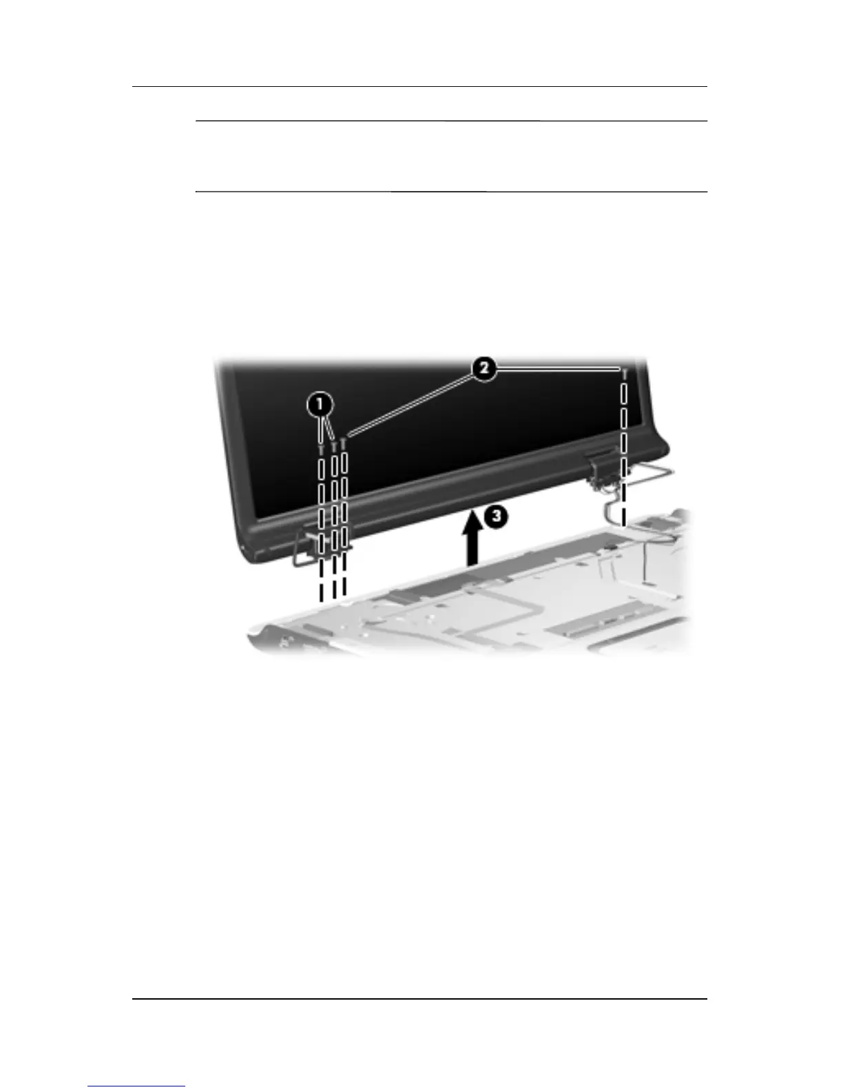
10. Remove the two Phillips PM2.5×8.0 screws 1 and the
two silver Phillips PM2.5×5.0 screws 2 that secure
the display assembly to the computer.
11. Remove the display assembly 3.
Removing the Display Assembly
 Loading...