EasyManuals Logo

HP Pavilion dv9000 Maintenance And Service Guide

HP Pavilion dv9000
300 pages
To Next Page IconTo Next Page
To Previous Page IconTo Previous Page
Page #135 background imageLoading...
Page #135 background image
5–22 Maintenance and Service Guide
Removal and Replacement Procedures
5.10 Switch Cover
1. Prepare the computer for disassembly (Section 5.3).
2. Close the computer.
3. Turn the computer upside down with the front panel
toward you.
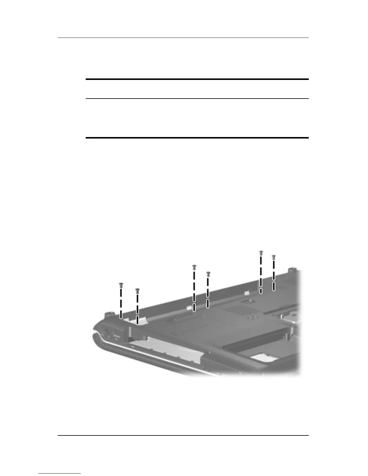
4. Remove the six Phillips PM2.0×5.0 screws that secure the
switch cover to the computer.
Removing the Switch Cover Screws
Switch Cover Spare Part Number Information
Switch cover (includes LED board and LED
board cable), for model dv9000
Switch cover (includes LED board and LED
board cable), for model dv9200
432979-001
442920-001

Table of Contents

Other manuals for HP Pavilion dv9000

Questions and Answers:

Question and Answer IconNeed help?

Do you have a question about the HP Pavilion dv9000 and is the answer not in the manual?

HP Pavilion dv9000 Specifications

General IconGeneral
Wireless802.11a/b/g
AudioAltec Lansing speakers
ProcessorIntel Core 2 Duo / AMD Turion 64 X2
Display17-inch WXGA+
GraphicsNVIDIA GeForce Go 7600
Operating SystemWindows Vista or Windows XP
Optical DriveDVD±RW
USB Ports3
PortsVGA, Ethernet
Card Reader5-in-1
RAM1 GB to 4 GB
BluetoothOptional

Related product manuals