Removal and Replacement Procedures
Maintenance and Service Guide 5–77
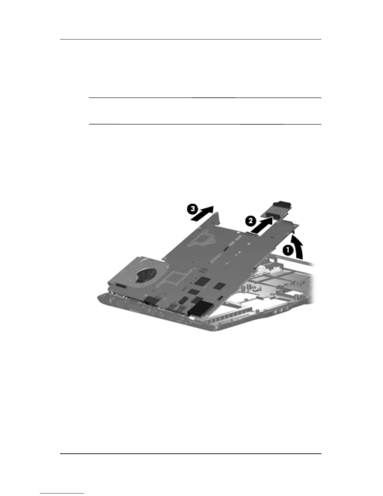
5. Lift the right side of the system board 1 until it rests at
an angle.
6. Remove the optical drive connector board 2.
✎
The optical drive connector board is available using spare part
number 432992-001.
7. Slide the system board 3 to the right until the connectors on
the left side of the system board disengage from the
base enclosure.
8. Remove the system board.
Removing the System Board
 Loading...