IP Routing Features
Configuring Static Network Address Translation (NAT) for Intranet Applications on the 5300xl Switches
Example. This example uses the topology in figure 11-30 on page 11-82:
■ The switch is connected to the corporate intranet through VLAN 100 (IP
address: 15.33.235.1).
■ The three devices are configured on VLAN 101 in the corporation’s
“private” region (IP address: 10.10.10.1) with these IP addresses:
A. 10.10.10.11
B. 10.10.10.12
C. 10.10.10.13
■ The system administrator selects these virtual IP addresses to make the
three devices appear to reside in the corporation’s “public” region:
A. 15.33.235.10
B. 15.33.235.32
C. 15.33.235.38
To configure the static NAT mapping between the actual IP addresses config-
ured on the devices and the corresponding virtual IP addresses:
HPswitch(config)# ip nat static 10.10.10.11 15.33.235.10
HPswitch(config)# ip nat static 10.10.10.12 15.33.235.32
HPswitch(config)# ip nat static 10.10.10.13 15.33.235.38
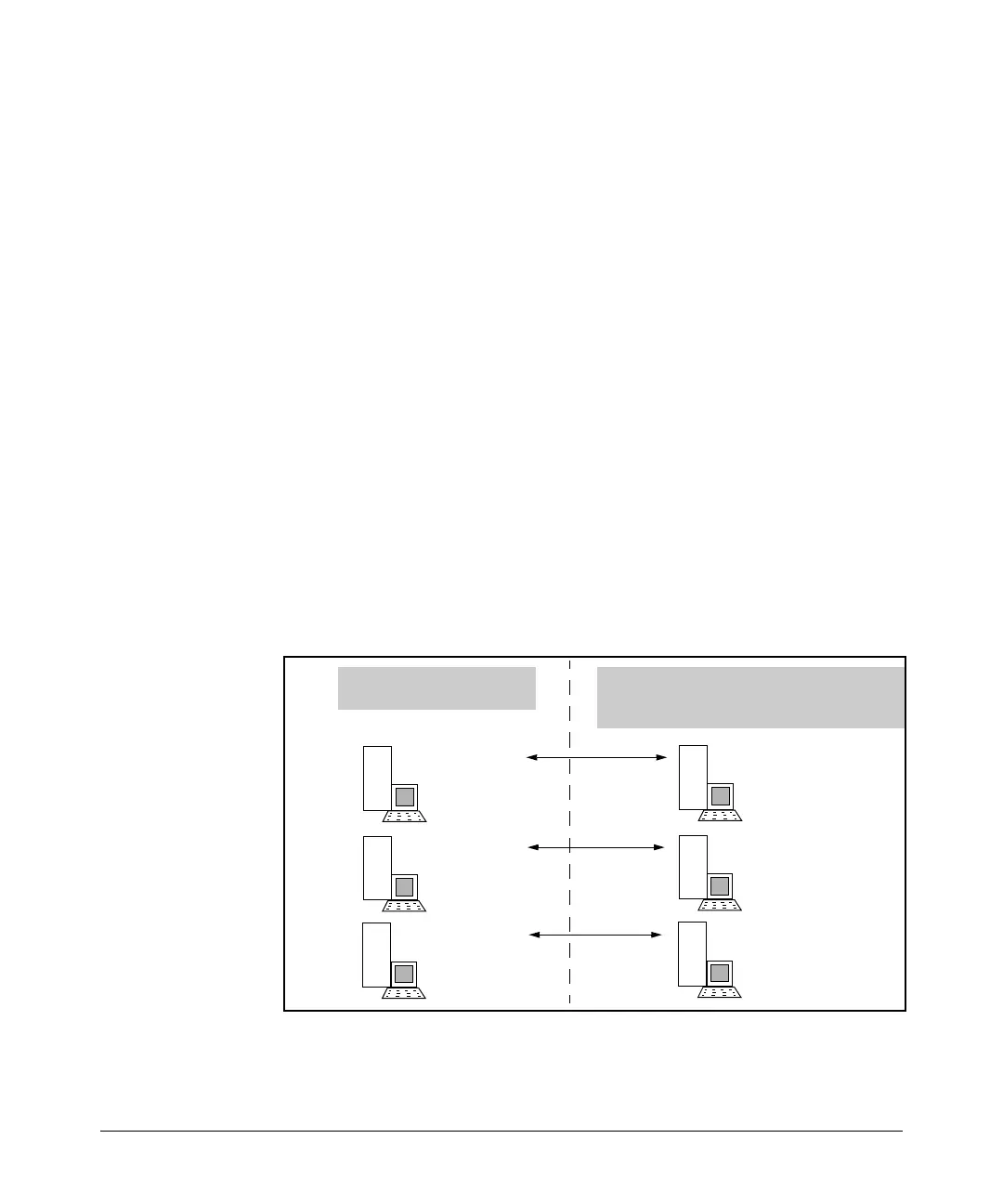
The above commands create the virtual IP address mappings in figure 11-31:
A: 10.10.10.11
B: 10.10.10.12
C: 10.10.10.13
The “Public” region within
the corporate intranet sees:
Static NAT conceals the actual IP addresses
configured on the devices in a “private” (hidden)
region within the corporate intranet.
A: 15.33.235.10
B: 15.33.235.32
C: 15.33.235.38
Figure 11-31.Example of Static NAT Mapping of Virtual IP Addressing
11-84
 Loading...