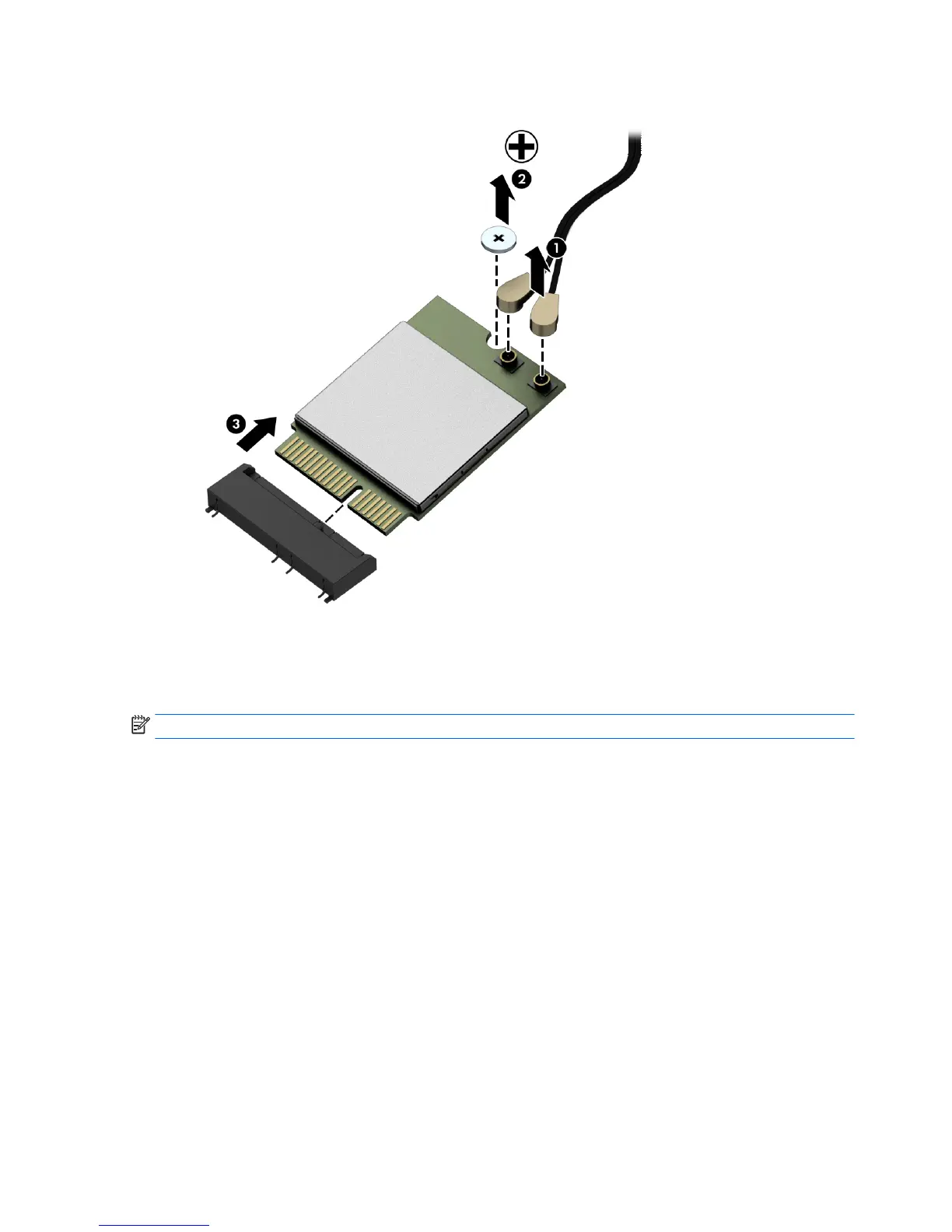
8. Lift the module to a 45-degree angle, and then pull it away to remove it from the socket (3).
To install the WLAN module, reverse the removal procedures.
When connecting the antennas cables, connect the cable labeled “1” (black sticker) to the AUX “1” connector
on the modul
e and the cable labeled “2” (white sticker) to the MAIN “2” connector on the module.
NOTE: WLAN modules are designed with a notch to prevent incorrect insertion.
44 Chapter 4 Removal and Replacement Procedures
 Loading...