Section III
Figure 3-2
Model 4342A
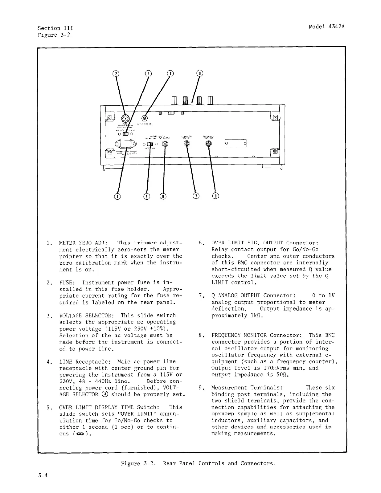
1.
2.
3.
4.
5.
METER ZERO AD<J: This trimmer adjust-
ment electrically zero-sets the meter
pointer so that it is exactly over the
zero calibration mark when the instru-
ment is on.
FUSE: Instrument power fuse is in-
stalled in this fuse holder. Appro-
priate current rating for the fuse re-
quired is labeled on the rear panel.
VOLTAGE SELECTOR: This slide switch
selects the appropriate ac operating
power voltage (115V or 230V +lO%).
Selection of the ac voltage must be
made before the instrument is connect-
ed to power line.
LINE Receptacle: Male ac power line
receptacle with center ground pin for
powering the instrument from a 115V or
23OV, 48 - 440Hz line. Before con-
necting power cord (furnished), VOLT-
AGE SELECTOR @ should be properly set.
OVER LIMIT DISPLAY TIME Switch: This
slide switch sets "OVER LIMIT" annun-
ciation time for Go/No-Go checks to
either 1 second (1 set) or to contin-
ous (00).
6.
7.
8.
9.
OVER LIMIT SIC. OUTPUT Connector:
Relay contact output for Go/No-Go
checks. Center and outer conductors
of this BNC connector are internally
short-circuited when measured Q value
exceeds the limit value set by the Q
LIMIT control.
Q .4NALOG OUTPUT Connector: 0 to 1v
analog output proportional to meter
deflection.
Output impedance is ap-
proximately 1kR.
FREQUENCY MONITOR Connector:
This BNC
connector provides a portion of inter-
nal oscillator output for monitoring
oscillator frequency with external e-
quipment (such as a frequency counter).
Output level is 17OmVrms min. and
output impedance is 50R.
Measurement Terminals: These six
binding post terminals, including the
two shield terminals, provide the con-
nection capabilities for attaching the
unknown sample as well as supplemental
inductors, auxiliary capacitors, and
other devices and accessories used in
making measurements.
1
Figure 3-2. Rear Panel Controls and Connectors.
3-4
 Loading...


