Model 4342A
3-10. MEASUREMENT TERMINALS.
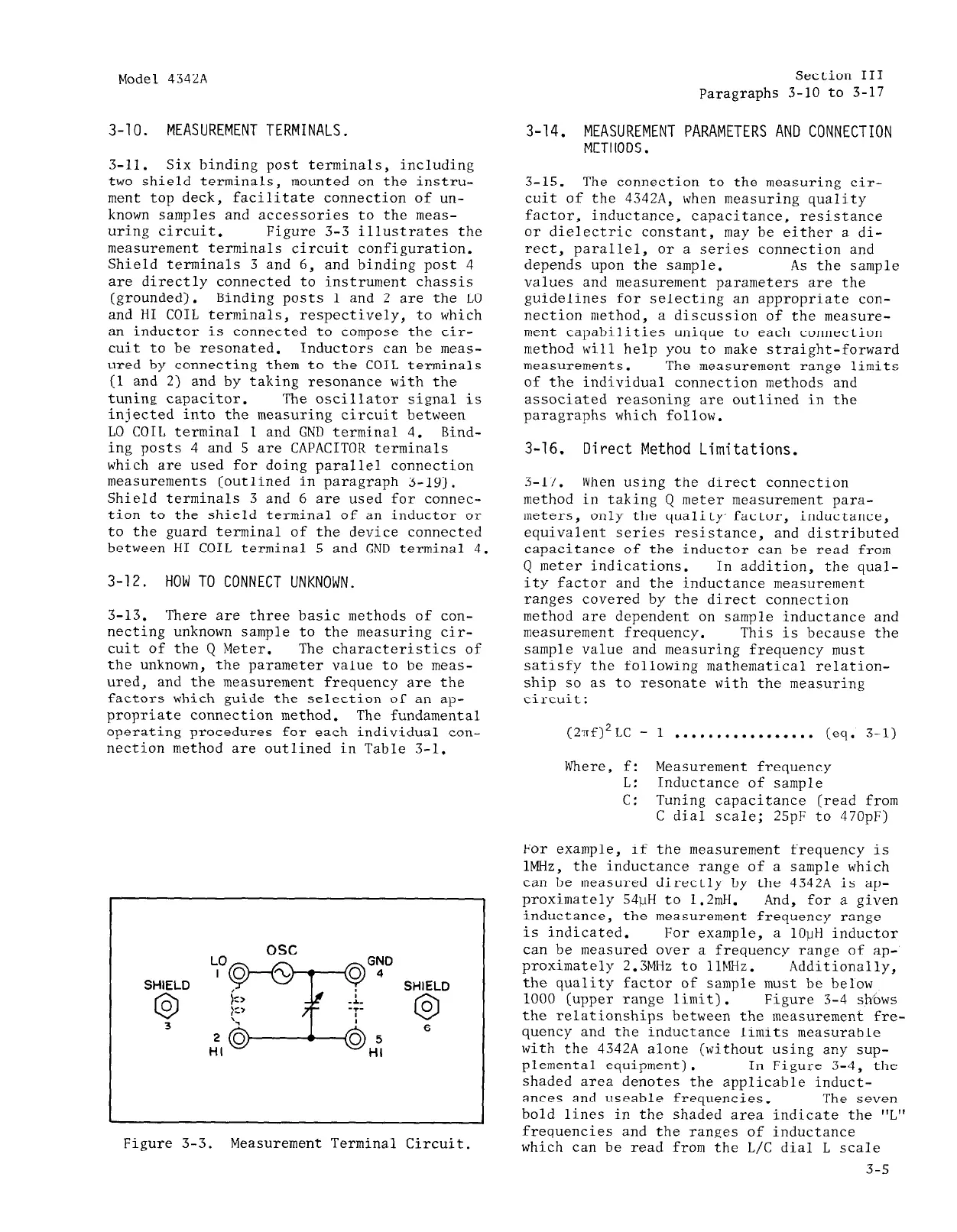
3-11. Six binding post terminals, including
two shield terminals, mounted on the instru-
ment top deck, facilitate connection of un-
known samples and accessories to the meas-
uring circuit. Figure 3-3 illustrates the
measurement terminals circuit configuration.
Shield terminals 3 and 6, and binding post 4
are directly connected to instrument chassis
(grounded). Binding posts 1 and 2 are the LO
and HI COIL terminals, respectively, to which
an inductor is connected to compose the cir-
cuit to be resonated. Inductors can be meas-
ured by connecting them to the COIL terminals
(1 and 2) and by taking resonance with the
tuning capacitor.
The oscillator signal is
injected into the measuring circuit between
LO COIL terminal 1 and GND terminal 4. Bind-
ing posts 4 and 5 are CAPACITOR terminals
which are used for doing parallel connection
measurements (outlined in paragraph 3-19).
Shield terminals 3 and 6 are used for connec-
tion to the shield terminal of an inductor or
to the guard terminal of the device connected
between HI COIL terminal 5 and GND terminal 4.
3-12. HOW TO CONNECT UNKNOWN.
3-13. There are three basic methods of con-
necting unknown sample to the measuring cir-
cuit of the Q Meter. The characteristics of
the unknown, the parameter value to be meas-
ured, and the measurement frequency are the
factors which guide the selection of an ap-
propriate connection method. The fundamental
operating procedures for each individual con-
nection method are outlined in Table 3-l.
SHIELD
0
0
3
SHIELD
0
0
6
Figure 3-3.
Measurement Terminal Circuit.
Section III
Paragraphs 3-10 to 3-17
3-14. MEASUREMENT PARAMETERS AND CONNECTION
METHODS.
3-15. The connection to the measuring cir-
cuit of the 4342A, when measuring quality
factor, inductance, capacitance, resistance
or dielectric constant, may be either a di-
rect, parallel, or a series connection and
depends upon the sample. As the sample
values and measurement parameters are the
guidelines for selecting an appropriate con-
nection method, a discussion of the measure-
ment capabilities unique to each connection
method will help you to make straight-forward
measurements. The measurement range limits
of the individual connection methods and
associated reasoning are outlined in the
paragraphs which follow.
3-16.
Direct Method Limitations.
3-17.
When using the direct connection
method in taking Q meter measurement para-
meters, only the quality' factor, inductance,
equivalent series resistance, and distributed
capacitance of the inductor can be read from
Q meter indications. In addition, the qual-
ity factor and the inductance measurement
ranges covered by the direct connection
method are dependent on sample inductance and
measurement frequency. This is because the
sample value and measuring frequency must
satisfy the following mathematical relation-
ship so as to resonate with the measuring
circuit:
(2Trf)2LC = 1 . . . . . . . . . . . . . . . . . (eq. 3-l)
Where, f: Measurement frequency
L: Inductance of sample
c:
Tuning capacitance (read from
C dial scale; 25pF to 470pF)
For example, if the measurement frequency is
lMHz, the inductance range of a sample which
can be measured directly by the 4342A is ap-
proximately 54uH to 1.2mH. And, for a given
inductance, the measurement frequency range
is indicated. For example, a 1OuH inductor
can be measured over a frequency range of ap-
proximately 2.3MHz to 11MHz. Additionally,
the quality factor of sample must be below
1000 (upper range limit). Figure 3-4 sh/ows
the relationships between the measurement fre-
quency and the inductance limits measurable
with the 4342A alone (without using any sup-
plemental equipment). In Figure 3-4, the
shaded area denotes the applicable induct-
ances and useable frequencies. The seven
bold lines in the shaded area indicate the "L"
frequencies and the ranges of inductance
which can be read from the L/C dial L scale
3-5