Section IV
Paragraphs 4-14 to 4-30
verter Q3-Q4 consists of a pair of emitter followers
connected in series which provides ahigher input im-
pedance and lower output impedance.
4-14. ALC AMPLIFIER(P/O A81
4-15. The ALC Amplifier circuit Q9-Q13 provides
the appropriate correction signal to the Oscillator
assembly(AlA1) in order to control the oscillator out-
put in accordance with the fixed reference dc level
set by the OX LEVEL control.
4-16. Q,‘nQ RANGE ATTENUATOR(A3)
4-17. The Q RANGE Attenuator consists of four
switches which provide a total attenuation of 30.4dB.
An additional switch is used for the AQ measurement.
The Meter Scale Indicator (Al 1) ganged with Q RANGE
switches, utilizes four lamps, two of these lamps are
used for the Q scale display and the other two for the
n Q scale. The attenuator output is fed to an Imped-
ance Converter(A4) which consists of transistors Ql
and Q2 and which is similar in operation to the one
described in paragraph 4-13.
4-18. TUNING CAPACITOR AND INJECTION
TRANSFORMER(A2)
4-19. The Tuning Capacitor sometimes referred to
as the Q Capacitor is an important part of the QMeter.
It is the reactance standard in the Q measurement.
Because the Q Capacitor can be calibrated precisely,
the Q Meter provides direct reading of inductance in
addition to Q. To achieve this high accuracy, the
capacitor is designed with low loss and low residual
inductance.
Minimum capacitance is low to maintain
accuracy at high frequencies. The Q Capacitor covers
a range of 2OpF to 475pF. Residual inductance is less
than 10nH.
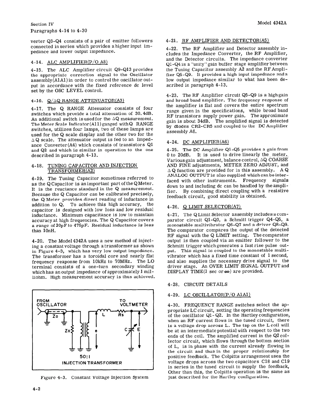
4-20. The Model4342A uses a new method of inject-
ing a constant voltage through a transformer as shown
in Figure 4-3, which has very low output impedance.
The transformer has a toroidal core and nearly flat
frequency reaponse from 1OkHz to 70MHz. The LO
terminal consists of a one-turn secondary winding
which has an output impedance of approximately 1 mil-
liohm. High measurement accuracy is thus achieved.
Model 4342A
4-21. RF AMPLIFIER AND DETECTOR(A5)
4-22. The RF Amplifier and Detector assembly in-
cludes the Impedance Converter, the RF Amplifier,
and the Detector circuits. The impedance converter
Ql-Q4is a”unity”gain buffer stage amplifier between
the Tuning Capacitor assembly A2 and the RFAmpli-
fier Q5-Q9. It provides a high input impedance and a
low output impedance similar to what has been de-
scribed in paragraph 4-13.
4-23. The RF Amplifier circuit Q5-Q9 is a highgain
and broad band amplifier. The frequency response of
the amplifier is flat and covers the entire spectrum
range given in the specifications, while broad band
RF transistors supply power gain. The approximate
gain is about 34dB. The amplified signal is detected
by diodes CR2-CR5 and coupled to the DC Amplifier
assembly A6.
4-24. DC AMPLIFIER(A6)
4-25. The DC Amplifier Ql-Q5 provides a gain from
0 to 20dB. It is used to drive linearly the meter.
Various gain adjustment, balance control, aQ COARSE
AND FINE adjustments, METER ZERO ADJUST, and
A Q function are provided for in this assembly. A Q
ANALOG OUTPUT is also supplied which can be inter-
faced with other instruments. Frequency signals
down to and including dc can be handled by theampli-
fier. By combining direct coupling with a resistive
feedback circuit, good stability is obtained.
4-26. Q LIMIT SELECTOR(A7)
4-27. The Q Limit Selector assembly includes acom-
parator circuit Ql-Q3, a Schmitt trigger Q4-Q5, a
monostable multivibrator Q6-Q7 and a driver Q8-Q9.
The comparator compares the output of the detected
RF signal with the Q LIMIT setting. Thecomparator
output is then coupled via an emitter follower to the
Schmitt trigger which generates a fast rise pulse out-
put.
This signal is coupled to the monostable multi-
vibrator which has a fixed time constant of 1 second,
and also supplies the necessary drive signal to the
driver stage. An OVER LIMIT SIGNAL OUTPUT and
DISPLAY TIME(l set Oreo) are provided.
4-28. CIRCUIT DETAILS
FROM
OSCILLATOR
yy$(Y-zq
Z-Y
50:1
1twcT10N TRANSFORMER
Figure 4-3. Constant Voltage Injection System
4-29. LC OSCILLATOR(P/O AlAl)
4-30. FREQUENCY RANGE switches select the ap-
propriate LC circuit, setting the operating frequencies
of the oscillator &l-&2. In the Hartley configuration,
when an RF current flows in the tuned circuit, there
is a voltage drop across L. The tap on the Lcoil will
be at an intermediatepotentialwith respect to the two
ends of the coil. The amplified current in the Q2coI-
lector circuit, which flows through the bottom section
of L, is in phase with the current already flowing in
the circuit and thus in the proper relationship for
positive feedback. The Colpitts arrangement uses the
voltage drops across the two capacitors Cl8 and Cl9
in series in the tuned circuit to supply the feedback,
Other than this, the Colpitts operation is the same as
just described for the Hartley configuration.
4-2