Section III
Paragraphs 3-18 to 3-23
Model 4342A
at these particular L frequencies. The induc-
tance at a measurement frequency other than
the "L" frequency can be determined by substi-
tuting frequency and L/C dial (C scale) read-
ings in equation 3-l.
3-18. Expansion of measurement ranges.
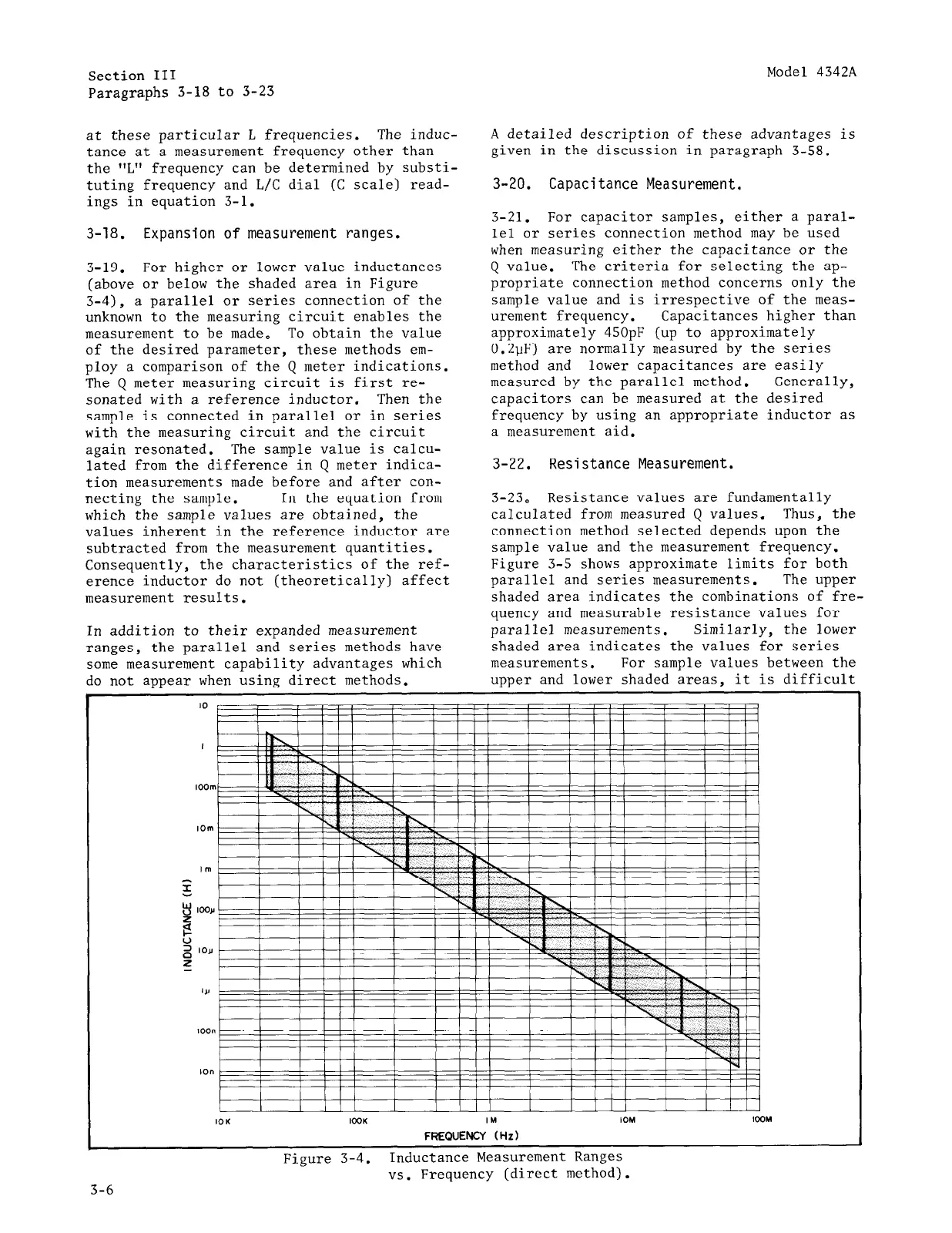
3-19.
For higher or lower value inductances
(above or below the shaded area in Figure
3-4), a parallel or series connection of the
unknown to the measuring circuit enables the
measurement to be made. To obtain the value
of the desired parameter, these methods em-
ploy a comparison of the Q meter indications.
The Q meter measuring circuit is first re-
sonated with a reference inductor.
Then the
sample is connected in parallel or in series
with the measuring circuit and the circuit
again resonated.
The sample value is calcu-
lated from the difference in Q meter indica-
tion measurements made before and after con-
necting the sample. In the equation from
which the sample values are obtained, the
values inherent in the reference inductor are
subtracted from the measurement quantities.
Consequently, the characteristics of the ref-
erence inductor do not (theoretically) affect
measurement results.
In addition to their expanded measurement
ranges,
the parallel and series methods have
some measurement capability advantages which
do not appear when using direct methods.
A detailed description of these advantages is
given in the discussion in paragraph 3-58.
3-20. Capacitance Measurement.
3-21. For capacitor samples, either a paral-
lel or series connection method may be used
when measuring either the capacitance or the
Q value. The criteria for selecting the ap-
propriate connection method concerns only the
sample value and is irrespective of the meas-
urement frequency. Capacitances higher than
approximately 450pF (up to approximately
0.2uF) are normally measured by the series
method and lower capacitances are easily
measured by the parallel method. Generally,
capacitors can be measured at the desired
frequency by using an appropriate inductor as
a measurement aid.
3-22. Resistance Measurement.
3-23. Resistance values are fundamentally
calculated from measured Q values. Thus, the
connection method selected depends upon the
sample value and the measurement frequency.
Figure 3-5 shows approximate limits for both
parallel and series measurements.
The upper
shaded area indicates the combinations of fre-
quency and measurable resistance values for
parallel measurements. Similarly, the lower
shaded area indicates the values for series
measurements. For sample values between the
upper and lower shaded areas, it is difficult
I I I III I I III I I III I I III
IOK lOOK
IM IOM l3OM
FREQUENCY (Hz)
Figure 3-4.
Inductance Measurement Ranges
vs. Frequency (direct method).
3-6