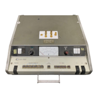
Model 4342A
Section IV
Paragraphs 4-l to 4-13
SECTION IV
THEORY OF
OPERATION
4-I. INTRODUCTION
4-2. This discussion of the HP Model4342A Q Meter
internal operation is divided into two parts: Block
diagram description and circuit description. The
block diagram section discusses the functions of the
major circuitswithin the instrument, using the over-
all block diagram. The circuit description provides
a detailed description of all the major circuits within
the instrument. It is suggested that the block diagram
and schematics which have been included in this manu-
al be referred to while reading the circuit description.
A Functional Overall Block Diagram of the instrument,
showing all the major circuits and associated relevant
information is provided in Section VIII at the back of
the manual. Also in Section VIII, there are complete
schematics of all the circuitry within the Model 4342A
which include components, reference designators, and
values.
4-3. Q DETERMINATION AND MEASUREMENT.
4-4. The ratio of a component’s reactance to its
resistance is measured by the Q meter. The magni-
tude of Q is usually considered a figure of merit ex-
pressing the ability of component to store energy
compared to the energy it dissipates. A measure of
Q is important to determine the RF resistance of
components, the loss angle of capacitors, dielectric
constants, transmission line parameters and antenna
characteristics, etc. Q is a dimensionless number.
In acircuit at resonance, &can bedefined as the ratio
of total energy stored to the average power dissipated
per cycle.
For a single reactance component:
Q = Xs/Rs = Rp/Xp
Where Xs and Xp are series and parallel reactance
and Rs and Rp are series and parallel resistance, The
most common form of Q meter uses a series resonant
circuit to measure Q, as shown in Figure 4-l.
4-5. When the variable air capacitor C is adjusted
so that Xc = XL, the only remaining impedance in the
loop is Rs.
The current that flows then is;
e
i=Fik
and the voltage E across capacitor C is;
E = &. Xc and-$=g=$$=
Q
This equation is correct for values of QZlO, for it
can be shown that the true
the Q meter is equal to
$y$y b,;~;pgfy~ ;;
held at a constant and known level, a voltmeier with
high input impedance can be connected across the
capacitor and calibrated directly in terms of Q. The
e values in the above equations are functions of se-
lected Q ranges. Rs is a function of the unknown in-
ductor or Q reference coils. A detailed explanation
for the measurement of unknowns is provided in
SECTION III.
4-6. SIMPLIFIED BLOCK DIAGRAM
4-7. The measurement principle used in the Model
4342A is the series resonant circuit. A simplified
block diagram of the Q Meter is shown in Figure 4-2.
The oscillator which covers 22kHz to 70MHz(lOkHz
to 32MHz in Option OOl), is automatically leveled by
a loop consisting of the detector and the ALC ampli-
fier. The oscillator output is controlledautomatically
by comparing it to a fixed dc level. Thus, constant
voltage is supplied to the Q-range attenuator.
The
attenuator adjusts the signal level according to the Q
range settings. This signal is fed into the resonant
circuit by a transformer (sometimes called an injec-
tion transformer). Resonance is acheived by adjusting
the variable capacitor, and this level is read by the
high-impedance voltmeter. Thus the Q value of the
resonant circuit is indicated on the meter.
4-8. BLOCK DIAGRAM DESCRIPTION
4-9. TheModel4342A Q Meter performsQmeasure-
ment in the range of 5 to 1000 on coils in seven bands
covering a frequency range from 22kHz to 70MHz
(1OkHz to 32MHz in Option 001). The following para-
graphs contain a brief outline of function of the major
circuit groups in the Q Meter. Reference is made to
the Functional Overall Block Diagram in SECTION
VIII.
4-10. OSCILLATOR AND IMPEDANCE
CONVERTER (AlAll
4-11. The Oscillator circuit QI-Q2 is a seven-band
variable frequency oscillator covering a frequency
range from 22kHz to 70MHz (1OkHz to 32MHz in Option
001). The instrument utilizes a Hartley type circuit
which operates from 22kHz to22MHz(lOkHz to 1OMHz
in Option OO1)and a Colpitts type circuit from 22MHz
to 70MHz(lOMHz to 32MHz in OptionOOl). The FRE-
QUENCY RANGE switch provides for the selection of
the desired band of operation. The output amplitude
of the oscillator is automatically controlled by an ALC
loop Q9-Q13(P/O A8) to provide the injection voltages
required by the Q ranges used. The oscillator output
is further coupled to a high impedance circuit Q3-Q6
which provides a buffer stage between the oscillator
and the RF power amplifier assembly.
4-12. RF POWER AMPLIFIER(AlA21
4-13. The RF Power Amplifier assembly consists of
a cascade amplifier circuit &l-Q2 with a gain of about
18dB and an impedance converter Q3-Q4. Commonly
called a cascade, the circuit uses an emitter grounded
amplifier followed by a grounded base stage. The
circuit has excellent noise figure, broadband charac-
teristics, and is very stable. The impedance con-
4-l

 Loading...