Model 4342A
Parallel Connection Measurements
Section III
Paragraphs 3-71 and 3-72
3-71. Dielectric Measurement.
3-72. The dielectric constant and dielectric
loss of insulating materials can be measured
by a method similar to and is basically a
capacitance measurement.
When a pair of
parallel electrodes (air capacitor) connected
to 4342A (in air) and an insulating material
placed between the electrodes, the electrode
capacitance increases in proportional to the
specific inductive capacity (ES) of the
sample material.
The dielectric constant of
the sample material is calculated as the pro-
duct of Es and the vacuum dielectric constant
CO.
Accordingly, the dielectric constant can
be determined from the capacitance measure-
ments made before and after placing the
sample between the elecrodes.
Additionally,
after the sample is mounted in the holder,
the conductance of the sample can also be
calculated from a reduction of the Q meter
indication. To make easy and accurate
dielectric measurements, it is recommended
that the 16451A Dielectric Test Adapter be
used with the 4342A.
Typical characteristics
of the 16451A are described in Table 3-2.
Materials to be measured with the 16451A
should be less than 1Omm in thickness and
from 38 to 55nn in diameter.
When measuring
materials with a high dielectric constant or
a large loss, it is usually best to prepare
material in thicknesses greater than 3nn.
On the other hand, when low loss material is
to be measured, the material thickness should
be less than 3mm.
Materials measuring less
than 0.5mm in thickness are usually difficult
to measure.
To make dielectric measurements using the
16451A, proceed as follows:
a.
b.
CO
d.
e.
f.
Depress the appropriate FREQUENCY
RANGE button and set FREQUENCY dial
control for the desired measurement
frequency.
Select a reference inductor which can
resonate at the measurement frequency.
Connect it to 4342A measurement COIL
(HI and LO) terminals.
Adjust L/C dial and AC dial controls
for a maximum Q meter deflection.
Note sum of the C dial and AC dial
readings as Cl and panel meter read-
ing as Qi.
Let the reference inductor remain in
place (as is) and attach the 16451A to
4342A measurement CAPACITOR (HI and
GND) terminals.
Set 16451A electrode spacing as de-
sired.
However, if possible, it is
best to set the electrode spacing
dimension to about the same as the
thickness of the material to be
measured.
Again resonate the measurement circuit
by adjusting the L/C and AC dial con-
trols.
Note C dial and AC dial read-
ings as C2 and panel meter reading Qa.
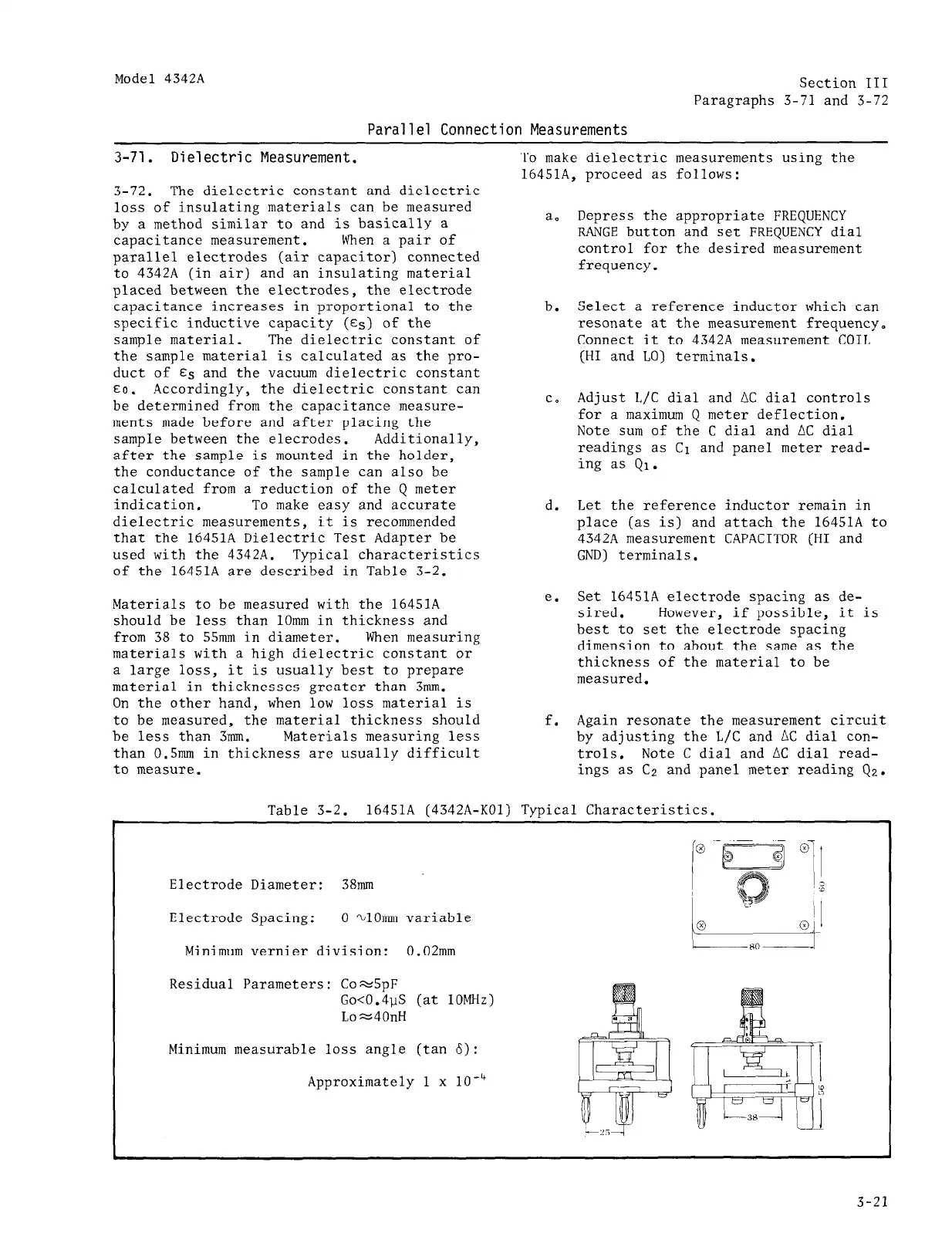
Table 3-2.
16451A (4342A-KOl) Typical Characteristics.
Electrode Diameter: 38mm
Electrode Spacing: 0 ~1Omm variable
Minimum vernier division: 0.02nm
Residual Parameters: Co=5pF
Go<0.4uS (at 1OMHz)
Loz40nH
Minimum measurable loss angle (tan 6):
Approximately 1 x 10e4
3-21