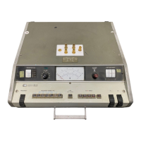
Model 43426 Table of Contents
Section Title Page
3-73. Series Measurements ................................
3-23
3-74. Low Inductance Measurement .................... 3-23
3-76. High Capacitance Measurement (>450pF) .........
3-24
3-78. Self-resonant Frequency Measurement
of High Capacitors .......................... 3-24
3-80. Low Resistance Measurement
....................
3-26
IV THEORY OF OPERATION ................................... 4-l
4-l.
Introduction.. ....................................... 4-1
4-3.
Q Determination and Measurement ..................... 4-l
4-6. Simplified Block Diagram ............................. 4-l
4-8. Block Diagram Description ...........................
4-l
4-10. Oscillator and Impedance Converter (AlAl) ....... 4-l
4-12.
RF Power Amplifier (AlA2) ..................... 4-l
4-14. ALC Amplifier (P/O A8)
........................
4-2
4-16. Q/AQ Range Attenuator (A3) .....................
4-2
4-18. Tuning Capacitor and Injection Transformer (A2). .. 4-2
4-21.
RF Amplifier and Detector (A5) .................. 4-2
4-24. DC Amplifier (A6)
..............................
4-2
4-26.
Q Limit Selector (A7) ...........................
4-2
4-28. Circuit Details
......................................
4-2
4-29. LC Oscillator (P/O AlAl) .......................
4-2
4-31. Impedance Converter (P/O AlAl) and RF
Power Amplifier (AlA2) .... 4-3
4-33.
ACL Amplifier (P/O A8) ........................ 4-3
4-35. Q Range Attenuator (A3)
........................
4-3
4-37.
Impedance Converter, RF Amplifier
and Detector (A5)
...... 4-3
4-39. DC Amplifier (A6) .............................. 4-3
4-41. Q Limit Selector (A7)
........................... 4-3
4-43. Power Supply (P/O ~8)
.........................
4-3
V MAINTENANCE
............................................
5-l
5-l.
Introduction ......................................... 5-l
5-3. Test Equipment Required ............................. 5-l
5-5.
Q Accuracy Considerations ........................... 5-l
5-7. Option .............................................. 5-l
5-9. Performance Checks
.................................
5-3
5-11. Frequency Accuracy Check..
....................
5-3
5-12.
QRange Check.. ............................... 5-3
5-13.
AQ Range Check ............................... 5-4
5-14. Capacitance Accuracy Check
....................
5-4
5-15. Q Limit Operation Check
........................ 5-5
5-16. Adjustment and Calibration Procedures ................
5-8
5-18.
Power Supply Adjustment
........................
5-8
5-19. Oscillator Level Adjustment
.....................
5-8
5-20. Oscillator Frequency Adjustment ................. 5-8
5-21.
Q Voltmeter Adjustment ........................ 5-9
5-22.
Q Analog Output Adjustment .....................
5-10
5-23. Frequency Response Adjustment
.................
5-11
5-24. Q Limit Selector Adjustment
.....................
5-11
5-25. Option 001 Maintenance Instructions
...................
5-12
5-27. Option 001 Performance Checks ..................
5-12
5-29. Option 001 Calibration and Adjustment Procedures . 5-13
5-31.
Dial Re-stringing Instructions .........................
5-14
5-34. Frequency Dial ................................. 5-14
5-35.
L/C Dial
......................................
5-14
5-36. AC Dial .......................................
5-14
5-37. Troubleshooting Guides ...............................
5-18
5-39. High Frequency Line Noise
......................
5-18
5-40.
Operating in a Strong Electromagnetic Field .......
5-18
5-41. Operating in High Humidity Environment .......... 5-18
. .
111

 Loading...