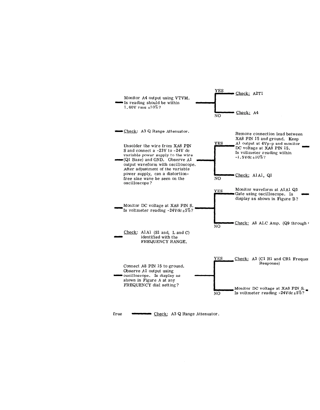
Monitor A4 output using VTVM.
-1s reading should be within
1.6OV rms *lo%?
YES
A2Tl Check:
NO
Check; A4
-Check: A3 Q Range Attenuator.
Unsolder the wire from XA8 PIN
S and connect a -23V to -24V dc
variable power supply to the wire
-(Ql Base) and GND. Observe Al
output waveform with oscilloscope
After adjustment of the variable
power supply, can a distortion-
free sine wave be seen on the
oscilloscope ?
-Monitor DC voltage at XA8 PIN S.
Is voltmeter reading -24Vdc +50/o?
YES
Remove connection lead between
XA8 PIN 15 and ground. Keep
‘.
-r
Al output at 4Vp-p and monitor
DC voltage at XA8 PIN 15. -
Is voltmeter reading within
-1. SVdc-llO%?
I
NO
Check; AlAl, Ql
YES
Monitor waveform at AlAl Q3
Gate using oscilloscope. Is -
display as shown in Figure B?
I
NO
Check: A8 ALC Amp. (Q9 through (
Check: AlAl (Sl and, L and C)
-
identified with the
FREQUENCY RANGE.
Connect A8 PIN 15 to ground.
Observe Al output using
-oscilloscope. Is display as
shown in Figure A at any
FREQUENCY dial setting ?
YES
Check: A3 (Cl Rl and CR1 Frequei
Response)
-c
Monitor DC voltage at XA8 PLN S. I
NO
Is voltmeter reading -24Vdc+5%?
rrue
- Check. A3 Q Range Attenuator.
d
 Loading...


