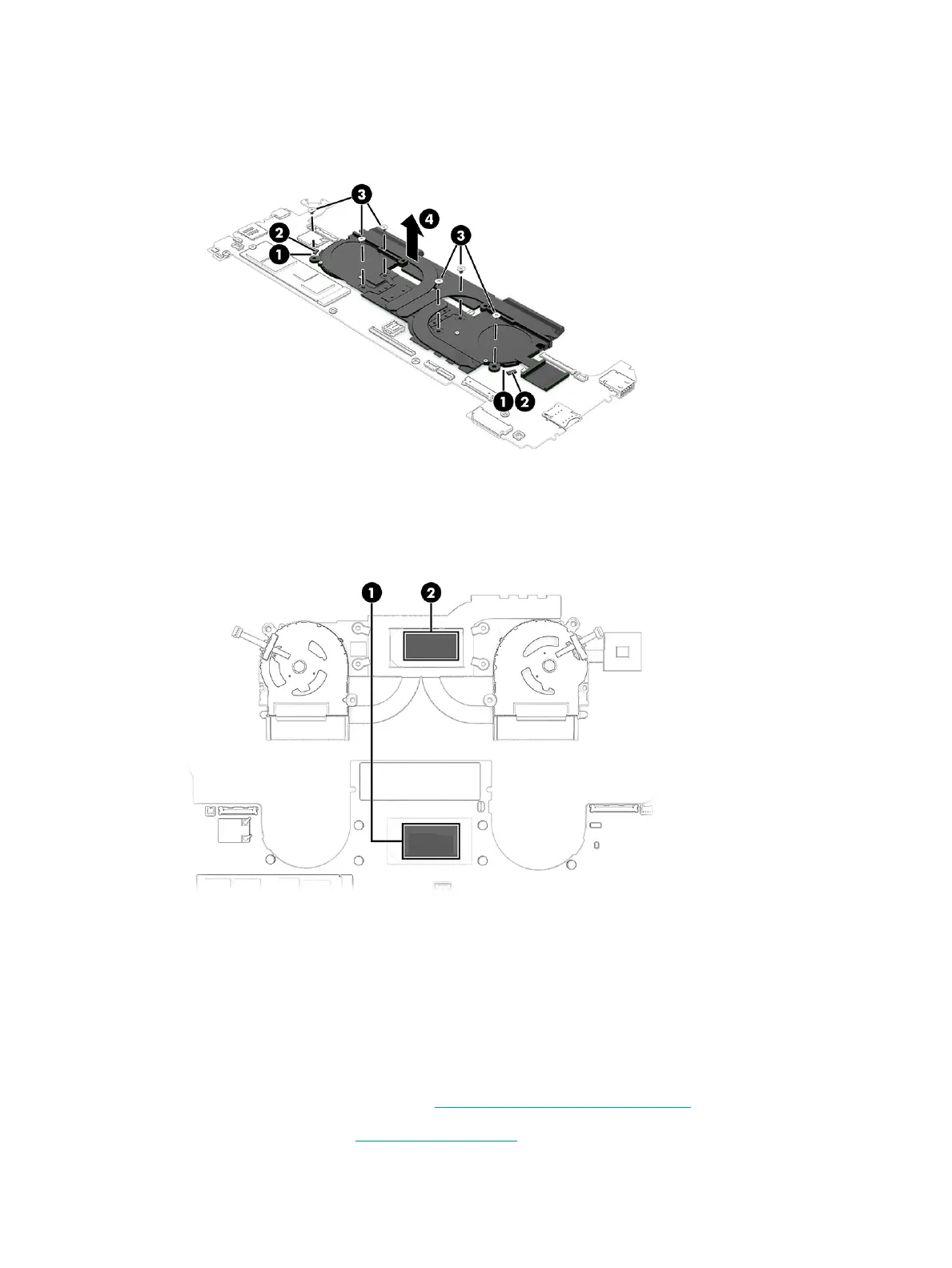
4. Remove the fan/heat sink assembly (4).
Each time the fan/heat sink assembly is removed, thoroughly clean the thermal material from the
processor component (1) and the surface of the fan/heat sink assembly (2). Replacement thermal material
is included with the fan/heat sink assembly and system board spare part kits.
Reverse this procedure to install the fan/heat sink assembly.
Connector board cable
To remove the connector board cable, use this procedure and illustration.
The connector board cable is available using spare part number M22150-001.
Before removing the connector board cable, follow these steps:
1. Prepare the computer for disassembly (Preparation for disassembly on page 37).
2. Remove the bottom cover (Bottom cover on page 37).
50 Chapter 5 Removal and replacement procedures for authorized service provider parts ENWW
 Loading...