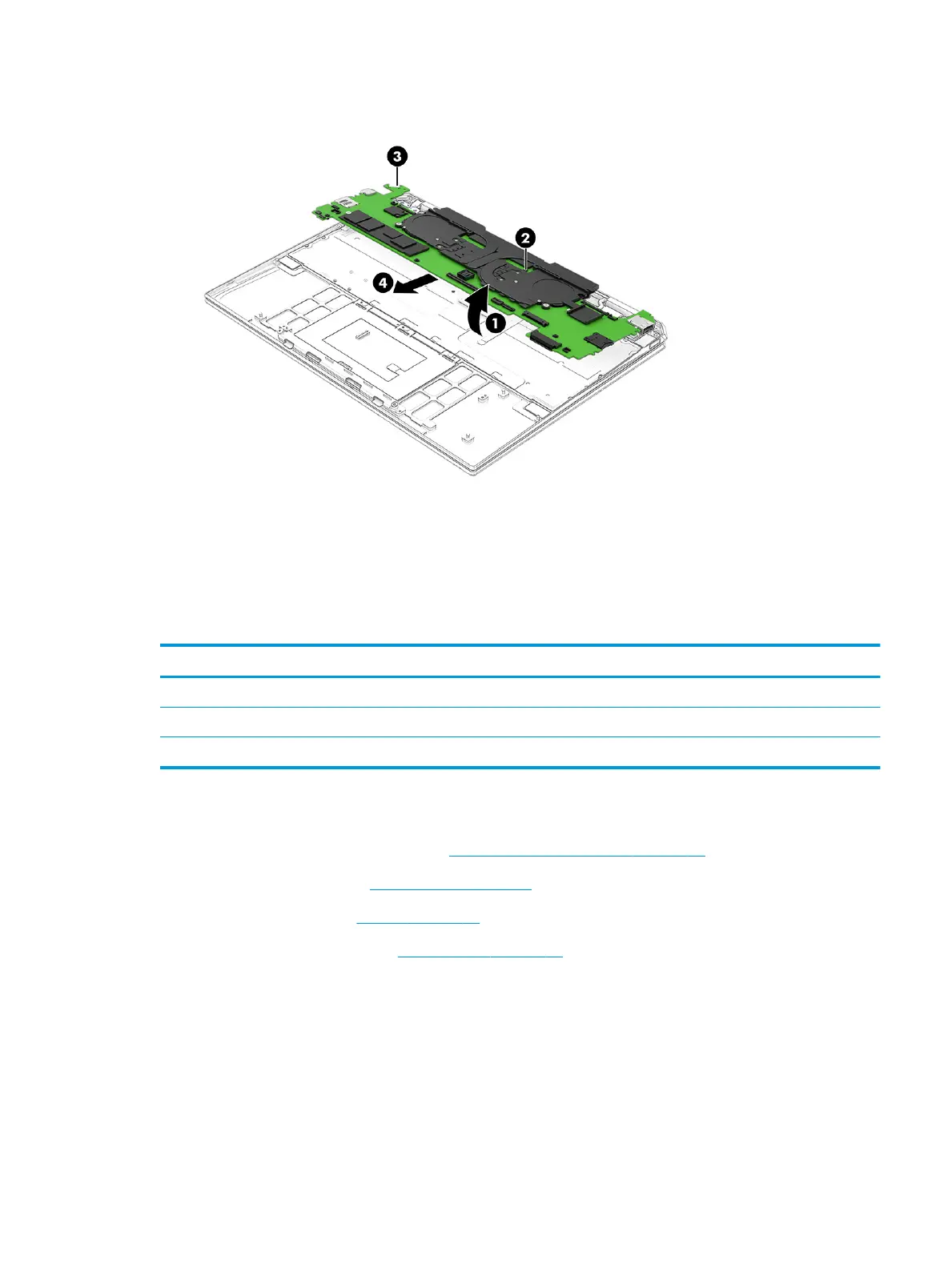
10. Remove the system board (4) by sliding it up and forward at an angle.
Reverse this procedure to install the system board.
Fan/heat sink assembly
To remove the fan/heat sink assembly, use these procedures and illustrations.
Table
5-8 Fan/heat sink assembly descriptions and part numbers
Description Spare part number
NOTE: The fan/heat sink assembly spare kit includes replacement thermal material.
For use only on computer models equipped with an OLED display assembly M22181-001
For use only on computer models equipped with a WLED display assembly M22180-001
Before removing the fan/heat sink assembly, follow these steps:
1. Prepare the computer for disassembly (Preparation for disassembly on page 37).
2. Remove the bottom cover (Bottom cover on page 37).
3. Remove the battery (see Battery on page 38).
4. Remove the system board (see System board on page 46).
Remove the fan/heat sink assembly:
1. Remove the fan shields (2 locations) (1) that secure the fan cables to the system board.
The fan shields are included in the Fan Shield Kit, spare part number M22153-001.
2. Disconnect the fan cables (2 locations) (2) from the system board.
3. Remove the six Phillips M2.0 × 2.0 screws (3) that secure the fan/heat sink assembly to the system board.
ENWW Component replacement procedures 49
 Loading...