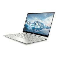
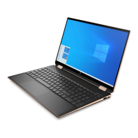
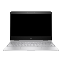
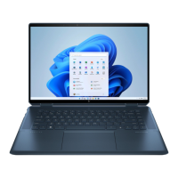
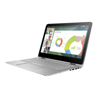
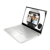
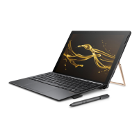
34.3 cm (13.5 in) display assembly
To remove and disassemble the display assembly, use these procedures and illustrations.
Table 5-5 Display assembly descriptions and part numbers
Description Spare part number
34.3 cm (13.5 in) display assembly:
Antiglare, WLED, touchscreen display assembly with privacy lter in natural silver nish; typical brightness:
1000 nits
M22161-001
Antiglare, WLED, touchscreen display assembly with privacy lter in nightfall black nish; typical brightness:
1000 nits
M22160-001
Antiglare, WLED, touchscreen display assembly with privacy lter in Poseidon blue nish; typical brightness:
1000 nits
M22162-001
BrightView, OLED, touchscreen display assembly in natural silver nish; typical brightness: 400 nits M22155-001
BrightView, OLED, touchscreen display assembly in nightfall black nish; typical brightness: 400 nits M22154-001
BrightView, OLED, touchscreen display assembly in Poseidon blue nish; typical brightness: 400 nits M22156-001
BrightView, WLED, touchscreen display assembly in natural silver nish; typical brightness: 400 nits M22158-001
BrightView, WLED, touchscreen display assembly in nightfall black nish; typical brightness: 400 nits M22157-001
BrightView, WLED, touchscreen display assembly in Poseidon blue nish; typical brightness: 400 nits M22159-001
Before removing the display assembly, follow these steps:
1. Prepare the computer for disassembly (Preparation for disassembly on page 37).
2. Remove the bottom cover (Bottom cover on page 37).
3. Disconnect the battery cable from the system board (see Battery on page 38).
Remove the display assembly:
1. Remove the heat sink shield (1).
2. Disconnect the webcam/microphone module cable (2) from the system board.
3. Remove the WLAN module shield (3).
4. Disconnect the wireless antenna cables (4) from the WLAN module.
NOTE: The #1/Main WLAN antenna cable connects to the WLAN module #1/Main terminal. The #2/Aux
WLAN antenna cable connects to the WLAN module #2/Aux terminal.
5. Release the webcam/microphone module cable and the WLAN antenna cables from the retention clip (5)
built into the top cover.
6. Disconnect the display panel cable (6) from the system board.
42 Chapter 5 Removal and replacement procedures for authorized service provider parts ENWW
 Loading...