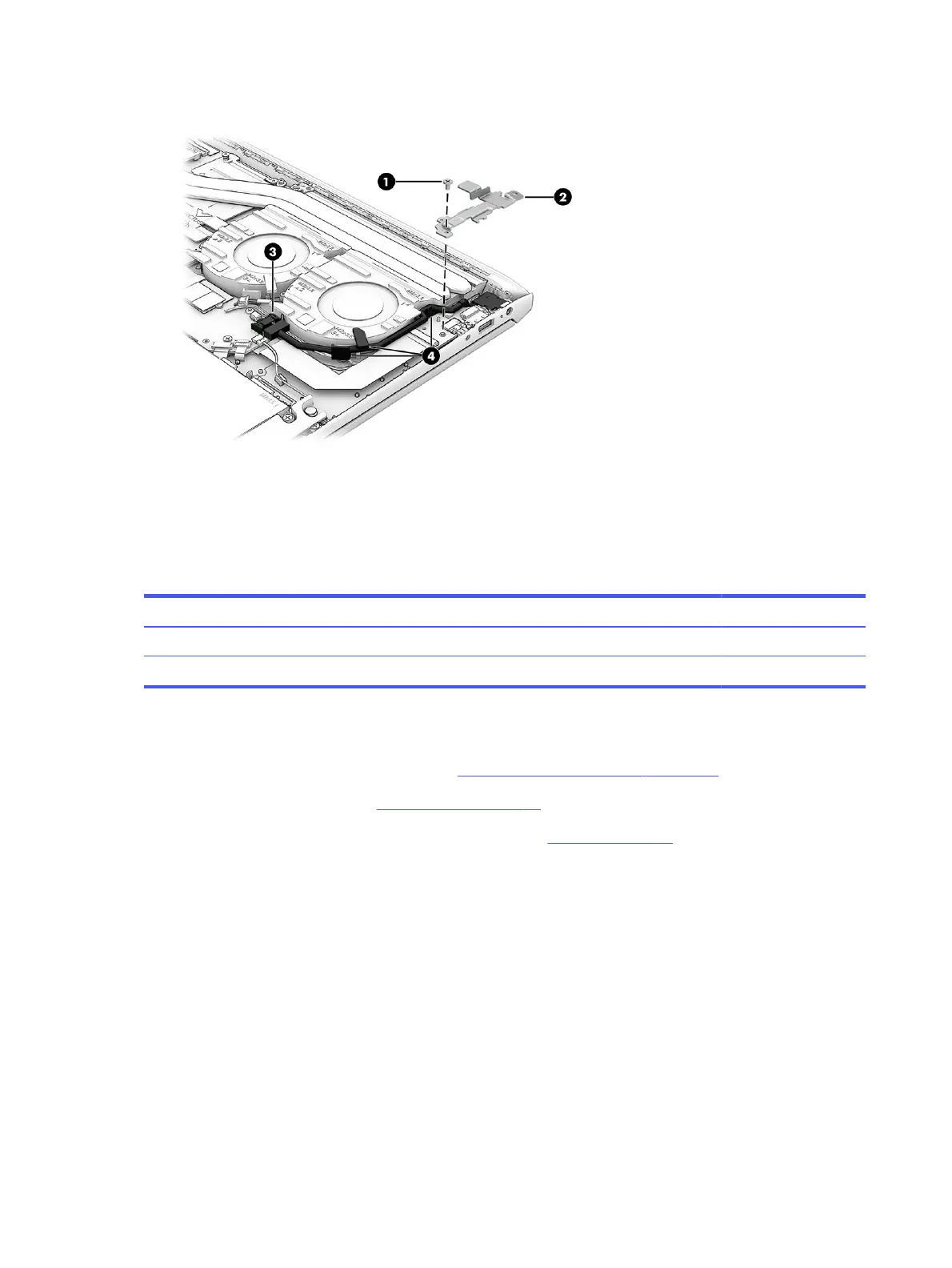
3. Remove the cable from the clips on the fan assembly (4).
To install the power connector cable, reverse this procedure.
I/O board
To remove the I/O board, use this procedure and illustration.
Table 6-7
I/O board description and part number
Description Spare part number
I/O board N13300-001
I/O board cable N13301-001
Before removing theI/O board, follow these steps:
1. Prepare the computer for disassembly (see Preparation for disassembly on page 37).
2. Remove the bottom cover (see Bottom cover on page 37).
3. Disconnect the battery cable from the system board (see Battery on page 39).
Remove the I/O board:
1. Remove the Phillips M2.0 × 3.0 screw (1) that secures the bracket to the computer, and then remove the
bracket (2).
2. Disconnect the cable from the ZIF connector on the I/O board (3).
48
Chapter 6Removal and replacement procedures for authorized service provider parts