To install theplastic rear vent and n, reverse this procedure.
Display assembly
To remove and disassemble the display assembly, use these procedures and illustrations.
NOTE: You can remove the bezel, display panel, and camera module without removing the entire display
assembly from the computer. For more information, see Display subcomponents (without removing the
display) on page 40. You do have to remove the display assembly to remove the remaining subcomponents.
Full hinge-up displays are not available as spare parts. Spare parts for displays are available only at the
subcomponent level.
Before removing thedisplay assembly, follow these steps:
1. Prepare the computer for disassembly (see Preparation for disassembly on page 37).
2. Remove the bottom cover (see Bottom cover on page 37).
3. Remove the battery (see Battery on page 39).
4. Remove the fan assembly (see Fan assembly on page 46).
5. Remove the I/O board bracket (see I/O board on page 48).
6. Remove the system board with heat sink installed (see System board on page 52).
7. Remove the plastic rear vent and n (see Plastic rear vent and n on page 56).
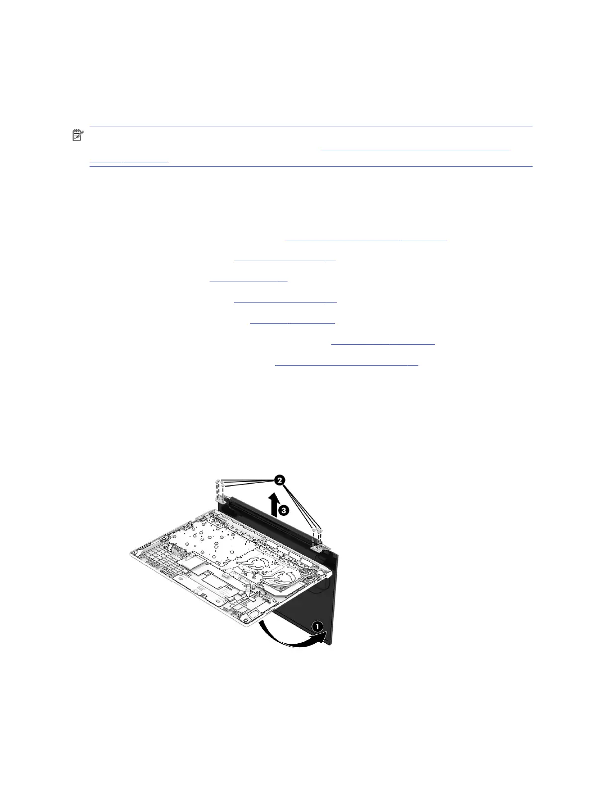
Remove the display assembly:
1. Open the display to open the hinges (1).
2. Remove the eight Phillips M2.6 × 4.5 screws (2) that secure the display assembly to the computer.
3. Separate the display from the computer (3).
4. If you need to remove the bezel:
a. Flex the top (1), the left and right sides (2), and then the bottom of the bezel (3) to release it.
58
Chapter 6Removal and replacement procedures for authorized service provider parts