Shenzhen Hpmont Technology Co., Ltd. Chapter 4 Electrical Installation
HD3L Series Controller User Manual ―19―
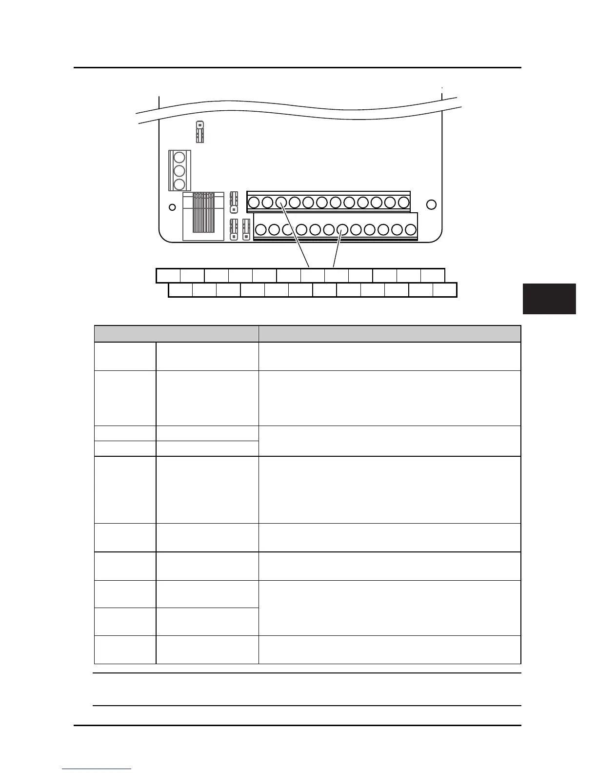
4.4.1 Control Board Terminal
Figure 4–4 Control board terminals
Table 4-5 Control board terminal description
Terminal Description
+10, GND Analogue power supply
Analogue input use +10V power supply, max. output current is 100mA
GND is isolated to COM
AI1, AI2 Analogue input
AI1 Input voltage: 0 - 10V (input impedance: 32kΩ)
AI2 Input voltage: -10 - +10V (input impedance: 32kΩ
)
AI2 Input current: 0 - 20mA (input impedance: 500Ω
)
• AI2 can select input voltage / current
AO1, AO2 Analogue output
Output voltage / current signal: 0 - 10V/0 - 20mA
Programmable output
GND Analogue ground
DI1 - DI6 Digital input
Programmable bipolar optional input signal
Input voltage: 0 - 30VDC
DI1 - DI5 input impedance 4.7kΩ, DI6 input impedance 1.6kΩ
• DI6 can be selectable for high-frequency input, max-frequency
50kHz
P24, COM Digital power supply
Analogue input use +24V power supply, max. output current is 200mA
COM is isolated to CME
SEL
Digital input common
terminal
SEL and P24 are connected by default
• Disconnected SEL and P24 when use external power to drive DI
DO1, CME Digital output
Programmable optical-couple isolation, open collector output
• Output voltage: 0 - 30VDC, max-output current 50mA
CME is isolated to COM, connected to COM by default
• Disconnect CME and COM when they are isolating output
DO2, COM Digital output
R1A/R1B/R1C Relay output
Programmable output, contact rating: 250VAC/3A or 30VDC/1A
• R1B, R1C: normally closed; R1A, R1C: normally open
Note:
Limit the current within 3A if the relay terminal is to connect to AC 220V voltage signal.
+10 AI1 AI2 DI1 DI2 DI3 DI4 DI5 DI6 COM R1ACOM
GND
AO1 AO2
P24 SEL DO1 R1CGND COM CME DO2 R1B
Control Board
Terminal
4
 Loading...
