EASYTEST-COMBI519
EN - 104
Depending on the set values of phase-phase, phase-neutral or phase-PE voltage (see §
5.1.3) and the measured value of fault loop impedance, the instrument calculates the
minimum value of the prospective short-circuit current to be interrupted by the protection
device. For proper coordination, this value MUST always be greater than or equal to the Ia
value of the tripping current of the type of protection considered as worst case
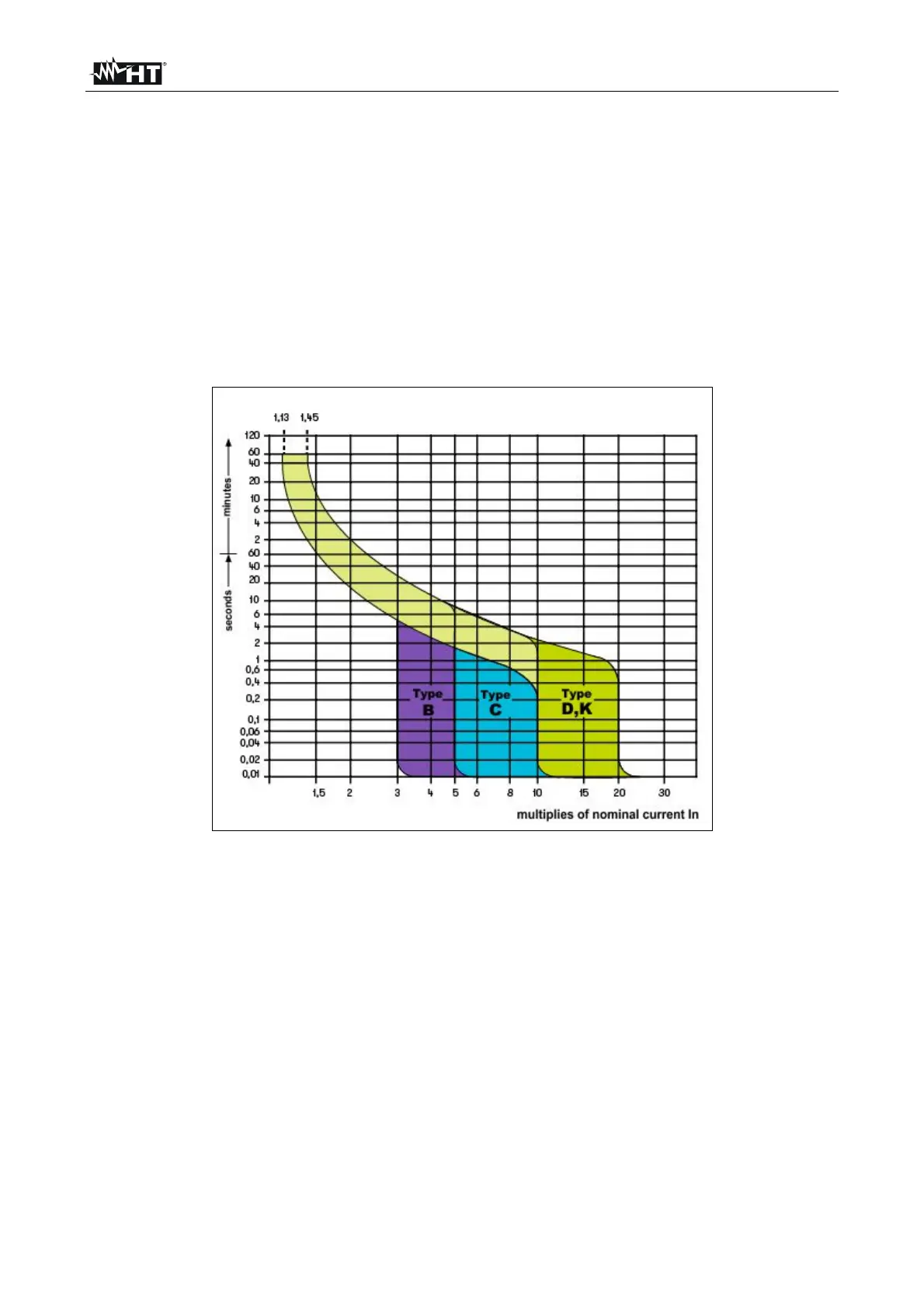
The Ia reference value (see Fig. 37) depends on:
Protection type (curve B, C, D, K)
Rated current of the protection device In
Time of fault extinction by the protection
Tipically: Ia = 3÷5In (curve B), Ia = 5÷10In (curve C), Ia = 10÷20In (curves D,K)
Fig. 37: Example of curves relative to magnetothermal (MCB) protection
The instrument allows the selection (*) of the following parameters:
MCB curve B 3A, 6A, 10A, 13A, 15A, 16A, 20A, 25A, 32A, 40A, 45A, 50A, 63A,
80A,100A,125A,160A,200A
MCB curve C 0.5A, 1A, 1.6A, 2A, 3A, 4A, 6A, 10A, 13A, 15A, 16A, 20A, 25A, 32A,
40A, 50A, 63A, 80A,100A,125A,160A,200A
MCB curve D, K 0.5A, 1A, 1.6A, 2A, 3A, 4A, 6A, 10A, 13A, 15A, 16A, 20A, 25A,
32A, 40A, 45A, 50A, 63A, 80A,100A,125A,160A,200A
Fuse gG 2A, 4A, 6A, 8A, 10A, 12A, 13A, 16A, 20A, 25A, 32A, 35A, 40A, 50A, 63A,
80A, 100A, 125A,160A, 200A, 250A, 315A, 400A, 500A, 630A, 800A, 1000A, 1250A
Fuse aM 2A, 4A, 6A, 10A, 12A, 16A, 20A, 25A, 32A, 35A, 40A, 50A, 63A, 80A,
100A, 125A,160A, 200A, 250A, 315A, 400A, 500A, 630A
Time of fault extinction by the protection selectable among: 0.1s, 0.2s, 0.4s, 1s, 5s
(*) The values could be subject to variations