EASYTEST-COMBI519
EN - 65
6.7.7. Ra 3-wire test - Verification of protection against indirect contacts
1.
Press the MENU key, move the cursor to AUTO in the
main menu by means of the arrow keys (,) and
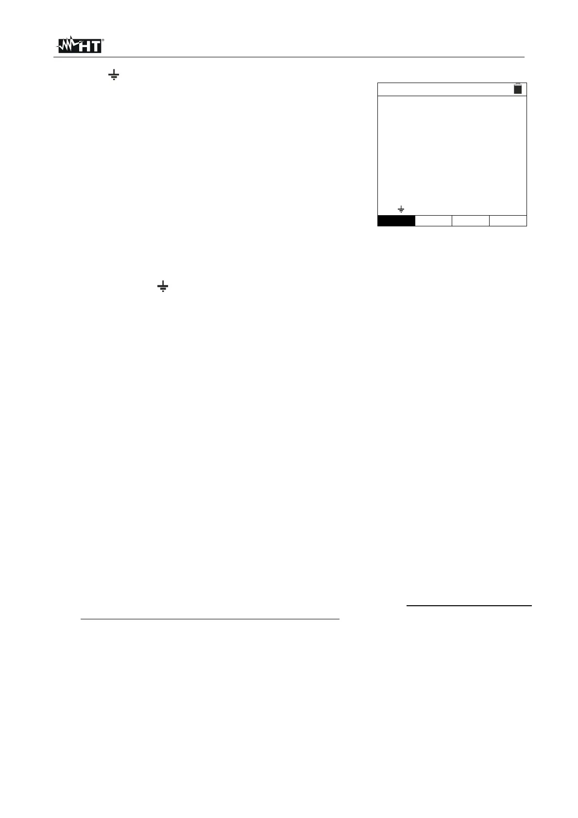
confirm with ENTER. Subsequently, the instrument
displays a screen similar to the one reported here to the
side. Select “Europe” as a country (see § 5.1.2), the
options “TN”, “25 or 50V”, “50Hz or 60Hz” and the
reference voltage in the general settings of the instrument
(see § 5.1.3).
NOTE: for countries different from “Europe”, the MCB
and Fuse reference type can be changed.
LOOP
15/10 – 18:04
TN
Isc=--- A ZL-N=--- Ω
Ifc=--- A ZL-PE=---Ω
FREQ=0.00Hz
VL-N=0V VL-PE=0V
Ra 3Wire 16A 0.2s
FUNC MODE MCB-C Time
2. Use the , keys to select the parameter to be modified, and the , keys to modify the
parameter value.
FUNC the virtual key allows setting the measuring mode of the instrument, which
may be: Ra
.
MODE the virtual key allows setting the instrument’s operating mode. Select the
3Wire option.
Type of protection the virtual key allows setting the type of protection (Fuse of
type gG, aM or magnetothermal MCB in curve B, C, D, K) and the relevant nominal
currents considering the below available values:
MCB curve B 3A, 6A, 10A, 13A, 15A, 16A, 20A, 25A, 32A, 40A, 45A, 50A, 63A,
80A, 100A, 125A, 160A, 200A
MCB curve C 0.5A, 1A, 1.6A, 2A, 3A, 4A, 6A, 10A, 13A, 15A, 16A, 20A, 25A,
32A, 40A, 50A, 63A, 80A, 100A, 125A, 160A, 200A
MCB curve D, K 0.5A, 1A, 1.6A, 2A, 3A, 4A, 6A, 10A, 13A, 15A, 16A, 20A, 25A,
32A, 40A, 45A, 50A, 63A, 80A, 100A, 125A, 160A, 200A
Fuse gG 2A, 4A, 6A, 8A, 10A, 12A, 13A, 16A, 20A, 25A, 32A, 35A, 40A, 50A,
63A, 80A, 100A, 125A,160A, 200A, 250A, 315A, 400A, 500A, 630A, 800A, 1000A,
1250A
Fuse aM 2A, 4A, 6A, 10A, 12A, 16A, 20A, 25A, 32A, 35A, 40A, 50A, 63A, 80A,
100A, 125A,160A, 200A, 250A, 315A, 400A, 500A, 630A
Time the virtual key allows to set type of protection tripping time among the
options: 0.1s, 0.2s, 0.4s, 1s, 5s
\ press SAVE key to save the selected parameter and retire to the measurement
screen
3. If possible, disconnect all loads connected downstream of the point to be measured, as
the impedance of these users could distort the test results. Perform the preliminary
calibration of the test leads as described in § 6.7.2
4. Insert the green, blue and black connectors of the three-pin plug cable into the
corresponding inputs B3, B4 and B1 of the instrument. As an alternative, use the single
cables and apply the relevant alligator clips to the free ends of the cables. It is also
possible to use the remote switch probe by inserting its multipolar connector into the
input B1. Connect the Mains Plug, the alligator clips or the remote switch probe to the
electrical mains according to Fig. 22, Fig. 23, Fig. 24, Fig. 25 or Fig. 26.