EASYTEST-COMBI519
EN - 64
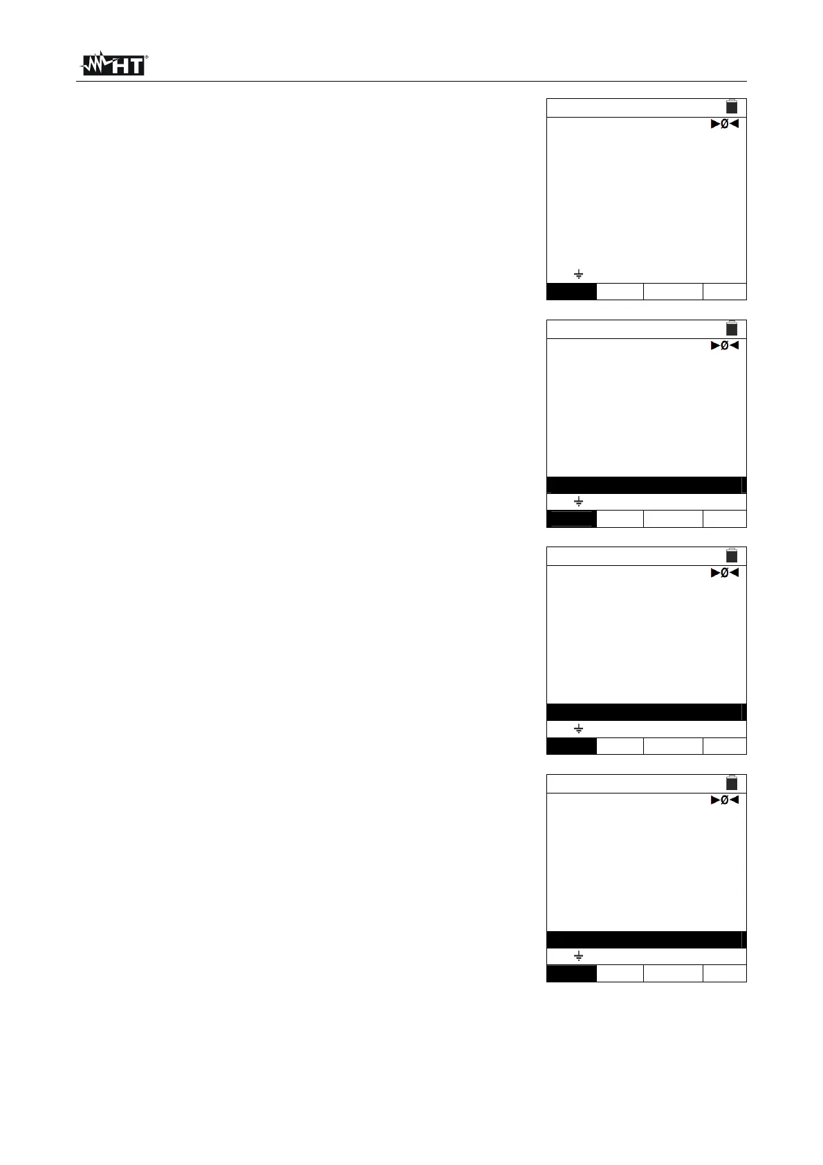
5. Note the presence of the correct voltage values between
L-PE corresponding to the selections carried out in the
initial phase (see § 5.1.3) as shown in the screen to the
side.
LOOP 15/10 – 18:04
TN
min
pfc
I
ZL-PE
=
=
- - -
- - -
A
FREQ. = 50.00Hz
VL-PE=223V
Ra 2Wire 16A 0.2s
FUNC MODE MCB-C Time
6.
Press the GO/STOP key on the instrument, the START
key on the remote switch probe or use the AutoStart
feature (see § 5.1.5). The instrument starts the
measurement and the “Measuring…” message is shown
at display. During this whole stage, do not disconnect the
measuring leads of the instrument from the system under
test. The following screen appears on the instrument's
display.
LOOP 15/10 – 18:04
TN
min
pfc
I
ZL-PE
=
=
- - -
- - -
A
FREQ. = 50.00Hz
VL-PE=223V
Measuring…
Ra 2Wire 16A 0.2s
FUNC MODE MCB-C Time
7.
In case of positive result (Z
L-PE
≤ to limit impedance
relative to protection device within the specified
time – see § 12.10), the “OK” message and the screen to
the side are displayed by the instrument.
LOOP 15/10 – 18:04
TN
min
pfc
I
ZL-PE
=
=
1213
0.18
A
FREQ. = 50.00Hz
VL-PE=223V
OK
Ra 2Wire 16A 0.2s
FUNC MODE MCB-C Time
8.
In case of negative result (Z
L-PE
> to limit impedance
relative to protection device within the specified
time – see § 12.10), the “NOT OK” message and the
screen to the side are displayed by the instrument.
LOOP 15/10 – 18:04
TN
min
pfc
I
ZL-PE
=
=
88
2.08
A
FREQ. = 50.00Hz
VL-PE=223V
NOT OK
Ra 2Wire 16A 0.2s
FUNC MODE MCB-C Time
9. Press the SAVE key to store the test result in the instrument’s memory (see § 7.1) or
the ESC/MENU key to exit the screen without saving and go back to the main
measuring screen.