EASYTEST-COMBI519
EN - 57
6.7.3. STD Mode – Generic test
This mode performs the impedance measurement and the calculation of prospective short-
circuit current without any evaluation. Therefore, at the end of the test, no outcome is given
by the instrument.
1.
Press the MENU key, move the cursor to LOOP in the
main menu by means of the arrow keys (,) and
confirm with ENTER. Subsequently, the instrument
displays a screen similar to the one reported here to the
side.
Select “Europe” as a country (see § 5.1.2), the options
“TN, TN or IT”, “25 or 50V”, “50Hz or 60Hz” and the
reference voltage in the general settings of the instrument
(see § 5.1.3).
LOOP 15/10 – 18:04
TN
Ipfc
ZL-PE
=
=
- - -
- - -
A
FREQ. = 0.00Hz
VL-PE=0V
VL-N=0V
L-PE STD
FUNC MODE
2. Use the , keys to select the parameter to be modified, and the , keys to modify the
parameter value.
FUNC the virtual key allows setting the measuring mode of the instrument, which
may be: L-N, L-L or L-PE.
MODE the virtual key allows setting the instrument’s operating mode. Select the
STD option.
3. If possible, disconnect all loads connected downstream of the point to be measured, as
the impedance of these users could distort the test results. Perform the preliminary
calibration of the test leads as described in § 6.7.2.
4. Insert the green, blue and black connectors of the three-pin plug cable into the
corresponding inputs B3, B4 and B1 of the instrument. As an alternative, use the single
cables and apply the relevant alligator clips to the free ends of the cables. It is also
possible to use the remote switch probe by inserting its multipolar connector into the
input B1. Connect the mains plug, the alligator clips or the remote switch probe to the
electrical mains according to Fig. 22, Fig. 23, Fig. 24, Fig. 25 or Fig. 26.
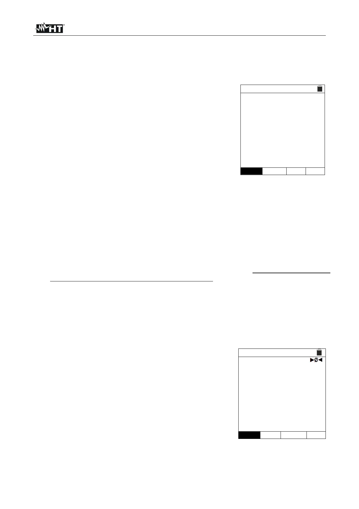
5. Note the presence of the correct voltage values between
L-N and L-PE corresponding to the selections carried out
in the initial phase (see § 5.1.3) as shown in the screen to
the side.
LOOP 15/10 – 18:04
TN
Ipfc
ZL-PE
=
=
- - -
- - -
A
FREQ. = 50.00Hz
VL-PE=231V
VL-N=232V
L-PE STD
FUNC MODE