EASYTEST-COMBI519
EN - 43
3. Insert the green, blue and black connectors of the three-pin plug cable into the
corresponding inputs B3, B4 and B1 of the instrument. As an alternative, use the
single cables and apply the relevant alligator clips to the free ends of the cables. It is
also possible to use the remote switch probe by inserting its multipolar connector into
the input B1. Connect the plug, the alligator clips or the remote switch probe to the
electrical mains according to Fig. 17, Fig. 18, Fig. 19, Fig. 20, Fig. 21.
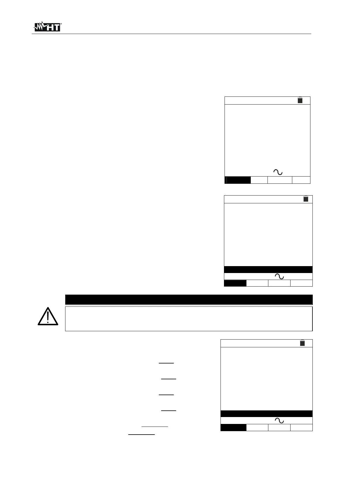
4. Note the correct voltage values between L-N and L-PE
as shown in the screen to the side.
RCD 15/10 – 18:04
TT
T
Ut
=
=
- - -
- - -
ms
V
FREQ. = 50.00Hz
VL-PE=232V
VL-N=231V
X1 30mA
+
MODE
In
Type Ut
6.6.1. AUTO mode
5.
Press the GO/STOP key on the instrument, the START
key on the remote switch probe or use the AutoStart
feature (see § 5.1.5). The instrument will start the
measurement.
RCD
15/10 – 18:04
TT
0° 180°
X1 38ms ---ms
X5 ---ms ---ms
X½ ---ms ---ms
FREQ=50.00Hz Ut=---V
VL-N=232V VL-PE=231V
Measuring...
AUTO 30mA
MODE
In
Type Ut
CAUTION
If message “Measuring…” appears on the display, the instrument is
performing measurement. During this whole stage, do not disconnect the
test leads of the instrument from the mains.
6.
The AUTO mode provides for the automatic execution of
6 measurements in a sequence:
IdN x 1 with phase 0° (the RCD must trip, reset the
switch, message “Resume RCD” is shown)
IdN x 1 with phase 180° (the RCD must trip, reset the
switch, message “Resume RCD” is shown)
IdN x 5 with phase 0° (the RCD must trip, reset the
switch, message “Resume RCD” is shown)
IdN x 5 with phase 180° (the RCD must trip, reset the
switch, message “Resume RCD” is shown)
IdN x½ with phase 0° (RCD must not trip)
IdN x½ with 180° (RCD must not trip, end of test)
RCD
15/10 – 18:04
TT
0° 180°
X1 38ms ---ms
X5 ---ms ---ms
X½ ---ms ---ms
FREQ=50.00Hz Ut=---V
VL-N=232V VL-PE=231V
Resume RCD
AUTO 30mA
MODE
In
Type Ut