EASYTEST-COMBI519
EN - 9
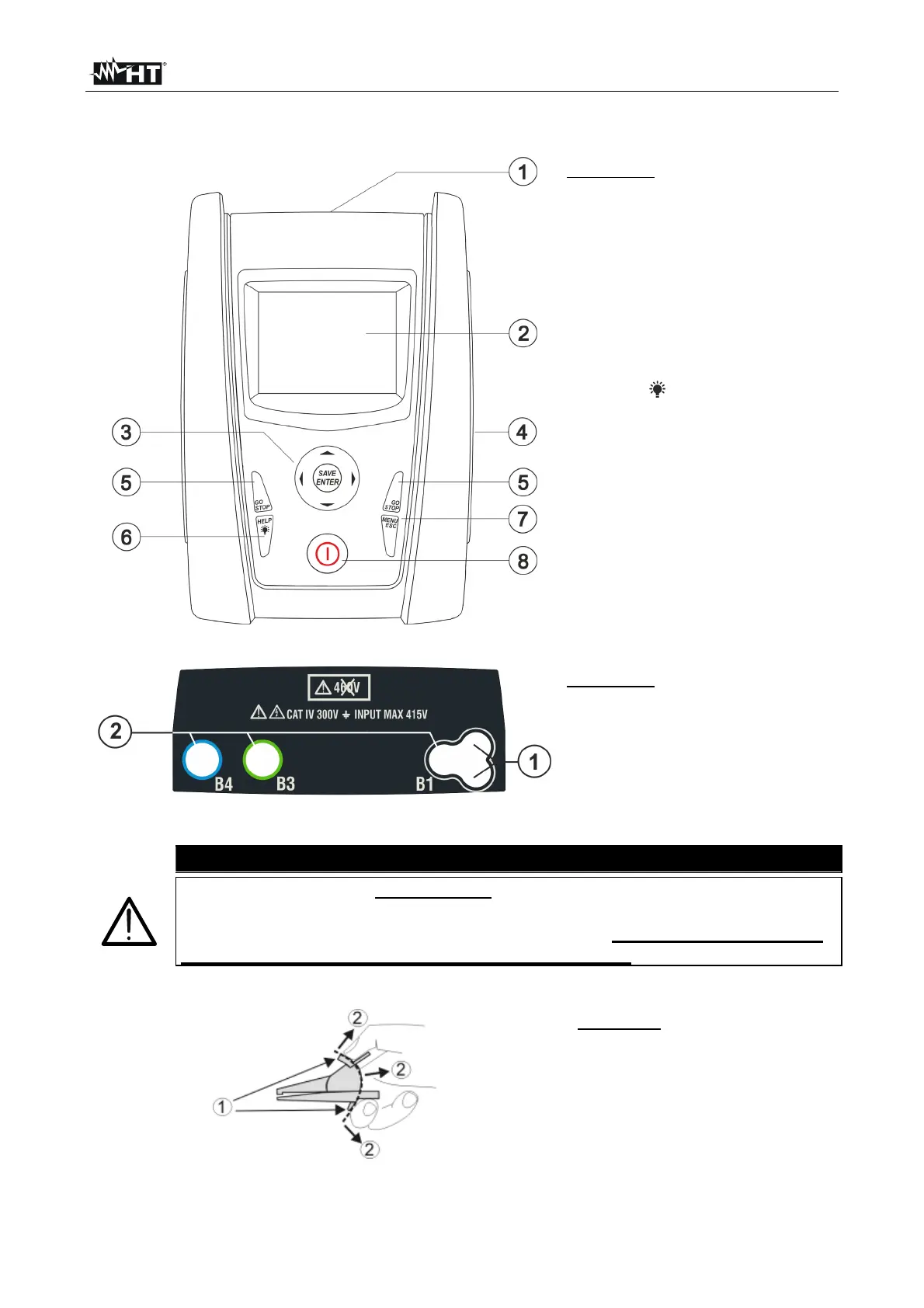
4. NOMENCLATURE
4.1. INSTRUMENT DESCRIPTION
CAPTION:
1. Inputs
2. LCD display
3. ,, , , SAVE/ENTER
keys
4. Compartment of the
connector for optical
cable/USB port
5. GO/STOP key
6. HELP/ key
7. ESC/MENU key
8. ON/OFF key
Fig. 1: Description of the front part of the instrument
CAPTION:
1. Connector for remote switch
probe
2. B1, B3, B4 inputs
Fig. 2: Description of the upper part of the instrument
CAUTION
The instrument checks voltage on PE by comparing the voltage at B4 input to
the ground potential induced on the instrument’s side through the user’s
hand. Therefore, in order to check voltage on PE, it is mandatory to hold
the instrument case on the left or on the right side.
4.2. DESCRIPTION OF MEASURING LEADS
CAPTION:
1. Hand protection
2. Safe area
Fig. 3: Description of measuring leads