EASYTEST-COMBI519
EN - 18
TT/IT systems
1.
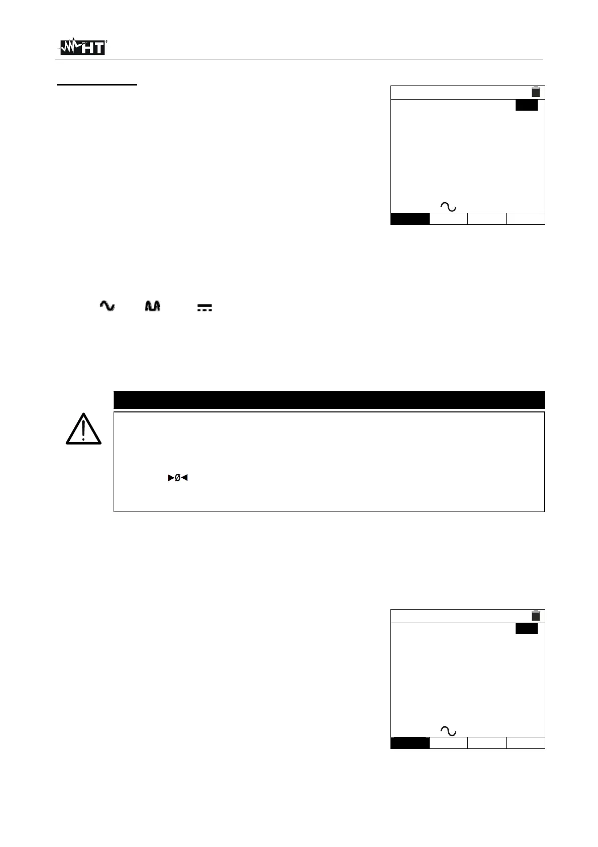
Press the MENU key, move the cursor to AUTO in the
main menu by means of the arrow keys (,) and
confirm with ENTER. Subsequently, the instrument
displays a screen similar to the one reported here to the
side.
Select “UK” as a country (see § 5.1.2), the options “TN”,
“25 or 50V”, “50Hz or 60Hz” and the reference voltage in
the general settings of the instrument (see § 5.1.3)
AUTO
15/10 – 18:04
TT >
<
RA=--- Ut=--- V
Trcd=---ms Ircd=---mA
FREQ=0.00Hz
VL-PE=0V VL-N=0V
30mA
500V
1.00M
In
Type Vtest Lim
2. Use the , keys to select the parameter to be modified, and the , keys to
modify the parameter value.
In The virtual key allows setting the nominal value of the RCD’s tripping
current, which may be: 6mA, 10mA, 30mA.
Type The virtual key enables the selection of the RCD type, which may be: AC
(
) , A ( ) or B ( )
Vtest This key allows selecting the DC test voltage generated during
measurement. The following values are available: 50V, 100V, 250V, 500V, 1000V.
Lim This key allows the selection of the minimum limit threshold in order to
consider the insulation measurement correct. The following values are available:
0.05M, 0.10M, 0.23M, 0.25M, 0.50M, 1.00M, 100M.
CAUTION
Make sure to select the correct value when setting the RCD’s test current.
If setting a current higher than the nominal current of the device being
tested, the RCD would be tested at a current higher than the correct one,
thus facilitating a faster tripping of the switch.
The “ ” symbol indicates that the test cables or the plug cablehas
already been calibrated in the LOOP section (see § 6.7). The AUTO
function takes this value as a reference.
3. Insert the green, blue and black connectors of the three-pin plug cable into the
corresponding inputs B1, B3 and B4 of the instrument. As an alternative, use the
single cables and apply the relevant alligator clips to the free ends of the cables. It is
also possible to use the remote switch probe by inserting its multipolar connector into
the input B1. Connect the plug, the alligator clips or the remote switch probe to the
electrical mains according to Fig. 4 or Fig. 5.
4. Note the correct voltage values between L-N and L-PE as
shown in the screen to the side.
AUTO
15/10 – 18:04
TT >
<
RA=--- Ut=--- V
Trcd=---ms Ircd=---mA
FREQ=50.00Hz Ut=---V
VL-PE=231V VL-N=232V
30mA
500V
1.00M
In
Type Vtest Lim
5.
Press the GO/STOP key on the instrument or the START key on the remote switch
probe. The instrument will start the automatic test sequence.