LP-387 Rev. 011 Rel. 005 Date 1.3.19
33
WHICHEVER IS GREATER
12" OVER MAXIMUM
SNOW LEVEL OR 24"
LP-445-G
06/23/15
SCREEN INTO
INSERT INLET/EXHAUST
STRAIGHT COUPLING
INSERT INLET/EXHAUST
SCREENS INTO
EACH END OF TEE
AND COUPLING (EXHAUST)
STRAIGHT
COUPLING
RIGHT SIDE VIEW
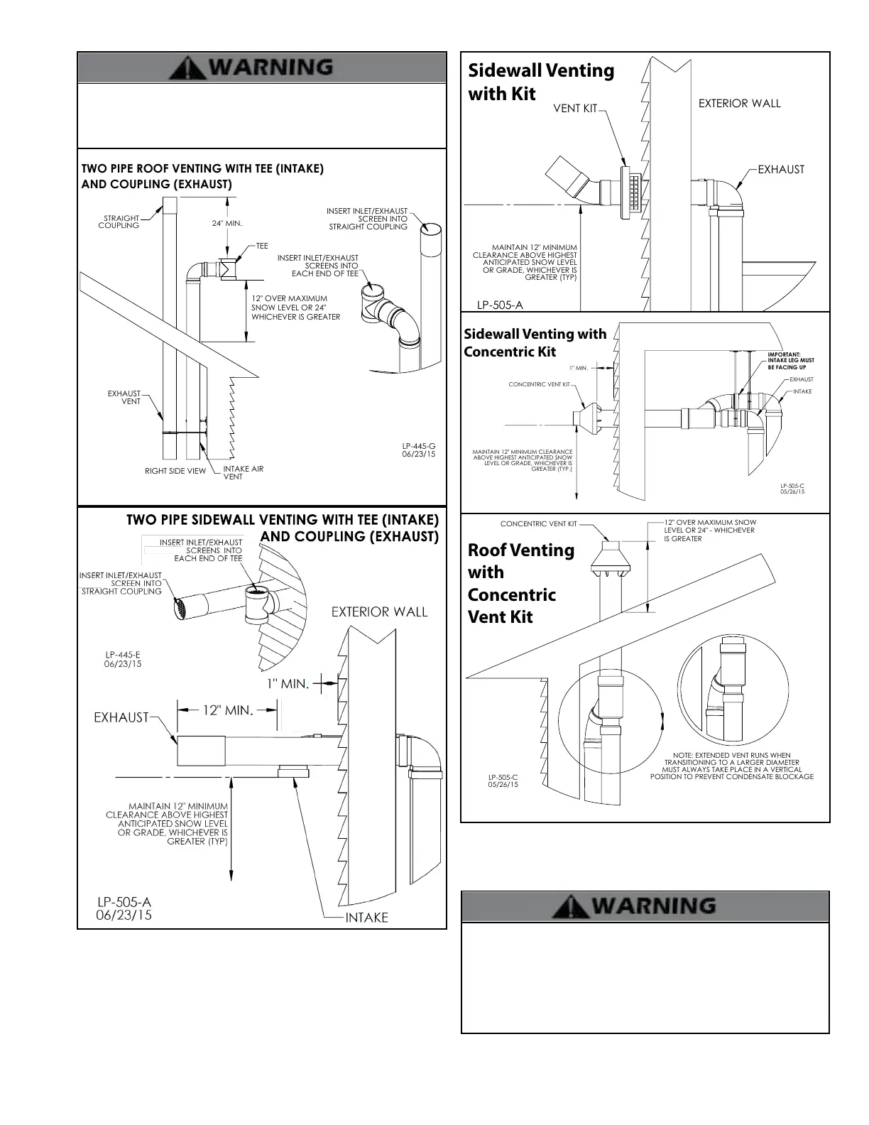
TWO PIPE ROOF VENTING WITH TEE (INTAKE)
TEE
EXHAUST
VENT
INTAKE AIR
VENT
24" MIN.
TWO PIPE SIDEWALL VENTING WITH TEE (INTAKE)
AND COUPLING (EXHAUST)
Figure 17 - Two Pipe Roof and Sidewall Venting
Take extra precaution to adequately support the weight of vent
pipes terminating through the roof. Failure to properly support roof
terminated piping could result in property damage, serious injury,
or death.
GREATER (TYP)
MAINTAIN 12" MINIMUM
CLEARANCE ABOVE HIGHEST
OR GRADE, WHICHEVER IS
VENT KIT
EXHAUST
ANTICIPATED SNOW LEVEL
EXTERIOR WALL
06/23/15
LP-505-A
Sidewall Venting
with Kit
05/26/15
LP-505-C
INTAKE
IMPORTANT:
EXHAUST
INTAKE LEG MUST
BE FACING UP
CONCENTRIC VENT KIT
MAINTAIN 12" MINIMUM CLEARANCE
ABOVE HIGHEST ANTICIPATED SNOW
LEVEL OR GRADE, WHICHEVER IS
GREATER (TYP.)
1" MIN.
Sidewall Venting with
Concentric Kit
12" OVER MAXIMUM SNOW
LEVEL OR 24" - WHICHEVER
IS GREATER
05/26/15
LP-505-C
CONCENTRIC VENT KIT
POSITION TO PREVENT CONDENSATE BLOCKAGE
NOTE: EXTENDED VENT RUNS WHEN
TRANSITIONING TO A LARGER DIAMETER
MUST ALWAYS TAKE PLACE IN A VERTICAL
Roof Venting
with
Concentric
Vent Kit
Figure 18 - Venting with Optional Kits (NOT INCLUDED WITH THE BOILER)
NOTE: These drawings are meant to demonstrate system venting only.
The installer is responsible for all equipment and detailing required by
local codes.
All vent pipes must be glued, properly supported, and the exhaust
pitched a minimum of 1/4” per foot back to the boiler to allow
drainage of condensate. When placing support brackets on vent
piping, the rst bracket must be within 1 foot of the boiler and the
balance of 4 foot intervals on the vent pipe. Venting must be readily
accessible for visual inspection from the rst three feet from the
boiler.

 Loading...