LP-387 Rev. 011 Rel. 005 Date 1.3.19
39
The condensate line must remain unobstructed. If allowed to freeze
in the line or obstructed in any other manner, condensate can exit
from the boiler tee, resulting in potential water damage to property.
When installing a condensate pump, select one approved for use
with condensing boilers and furnaces. The condensate pump should
have an overow switch to prevent property damage from spillage.
Condensate from the boiler will be slightly acidic (pH from 3.2 to 4.5).
Install a neutralizing lter if required by local codes.
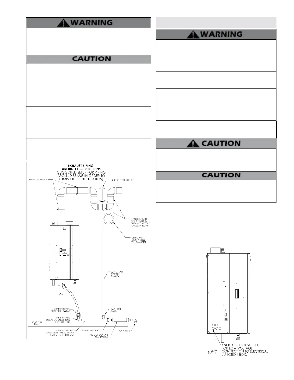
Is is very important that condensate piping be no smaller than 3/4”.
Use a tee at the condensate connection with a branch vertically
up and open to the atmosphere to prevent a vacuum that could
obstruct the ow of condensate from the boiler. To prevent sagging
and maintain pitch, condensate piping should be supported with
pipe supports.
When installing a condensate pump, select one approved for use
with condensing boilers and furnaces. The pump should have an
overow switch to prevent property damage from condensate
spillage.
Power to the optional condensate pump is continuous. When the
boiler is powered o the condensate pump will remain on. It is
important to remember to turn o the condensate pump when
powering down the boiler. Failure to do so could result in property
damage, severe personal injury, or death.
Figure 27 - Piping Exhaust Around Obstructions - Suggested Condensate
Removal
Part 7 - Wiring
To avoid electrical shock, turn o all power to the boiler prior
to opening an electrical box within the unit. Ensure the power
remains o while any wiring connections are being made. Failure
to follow these instructions could result in component or product
failure, serious injury, or death. Such product failure IS NOT
covered by warranty.
Jumping out control circuits or components WILL VOID product
warranty and can result in property damage, personal injury, or
death.
Label all wires prior to disconnecting them when servicing the
boiler. Wiring errors can cause improper and dangerous operation.
Failure to follow these instructions may result in property damage
or personal injury.
It is of extreme importance that this unit be properly grounded. It
is very important that the building system ground is inspected by
a qualied electrician prior to making this connection. Electrical
power must only be turned on when the boiler is completely lled
with cold water. Failure to follow these instructions could result in
component or product failure, serious injury, or death.
Electrical Shock Hazard - Turn o electrical power supply at
service entrance panel before making any electrical connections.
Failure to follow do do so could result in serious injury, or death.
Wiring must be NEC Class 1. If original wiring supplied with the
boiler must be replaced, use only TEW 105
o
C wire or equivalent.
Boiler must be electrically grounded as required by the National
Electrical Code, ANSI/NFPA 70 - Latest Edition.
A. Installation Must Comply With
1. National Electrical Code and any other national, state, provincial,
or local codes or regulations.
2. In Canada, CSA C22.1, Canadian Electrical Code Part 1, and any
local codes.
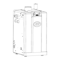
B. Field Wiring Terminations
All connections made to the boiler in the eld are done inside
the electrical junction
box located on the left
side of the unit. Multiple
knockout locations are
available to route eld
wires into and out of the
electrical junction box.
C. Field Wiring
The control used in
the boiler is capable of
directly controlling 1
pump in standard mode
and 2 pumps when
congured as a cascade
master boiler. As a
standard unit, each pump
can provide a maximum
of 4 amps at 120 volts. If a
pump requires more than
this amount of power,
an external contactor or
motor starter is needed.
Figure 28 - Knockout Locations

 Loading...