LP-387 Rev. 011 Rel. 005 Date 1.3.19
55
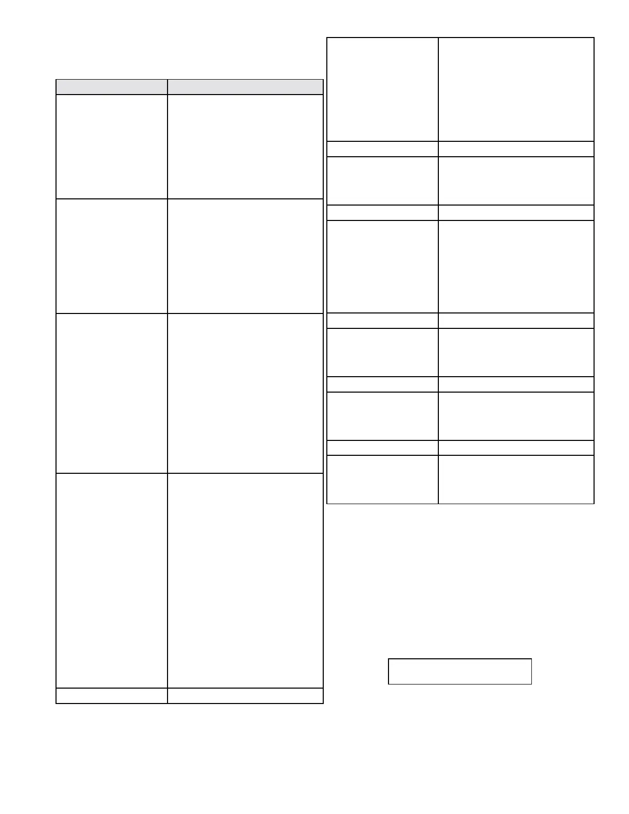
Screen Description
CASCADE MASTER READY
SYS PUMP OFF
This screen displays when the boiler
is congured as a Cascade Master and
the system is ready to accept a demand
for heat. The second line indicates the
cascade system pump output status.
This screen alternates with the default
screen every 5 seconds or can be
accessed by pressing the < key from
the default screen.
CASCADE NO FOLLOWER
SYS PUMP OFF
This screen displays when the boiler
is congured as a Master Boiler and
there are no connected follower
boilers, or the follower boilers are not
powered. The second line indicates
cascade system pump output status.
This screen alternates with the default
screen every 5 seconds or can be
accessed by pressing the < key from
the default screen.
CASCADE NO SENSOR
SYS PUMP OFF
This screen displays when the boiler
is congured as a Master Boiler and
there is no system temperature sensor
connected or the system sensor is
defective. The cascade system will
still function in this situation with
reduced eciency. All boilers will run
simultaneously rather than in a staged
fashion. The second line indicates
cascade system pump output status.
This screen will alternate with the
default screen every 5 seconds or can
be accessed by pressing the < key
from the default screen.
CASCADE TT 0123 567
SYS PUMP ON 12:47P
This screen displays information
about cascade status. The TT in the
center of the top line shows that
cascade demand is coming from the
TT contact being closed. You may
also see DHW if the demand is from a
DHW sensor, or 0-10 if the demand is
from a 0-10 volt input. The following
numbers show which boiler addresses
are currently communicating to
the master. If a boiler address is not
used or communicating, the number
will not display. In the example to
the left, boiler address #4 is not
communicating. When a boiler in the
system is ring, its address number will
alternate with a ‘.’ to signify it is ring.
The bottom line shows the status of
the system pump output contacts.
Press v once.
CASCADE PWR 100%
PRESENT 01234567
This screen displays overall cascade
power output. The range of this value is
the number of boilers communicating
with the Master x 100. For example,
if 8 boilers are connected and ring,
the maximum cascade power is 800%.
The second line shows which boiler
addresses are communicating with
the Master.
Press v once.
CASCADE SYST 118
o
F
CASCADE SET 190
o
F
This screen displays current system
temperature sensor reading on the
top line and the cascade system
temperature setting on the bottom.
Press v once.
BOILER 0 100%
BOILER 1 56%
This screen displays the current
cascade power demand output on a
per connected boiler basis for boilers
addressed as 0 and 1. In the example,
boiler 0 is being commanded to re at
100% and boiler 1 at 56%. If this were
a 2 boiler system, the ‘CASCADE PWR’
screen above would read 156%.
Press v once.
BOILER 2 0%
BOILER 3 0%
This screen displays the current
cascade power demand output on a
per connected boiler basis for boilers
addressed as 2 and 3.
Press v once.
BOILER 4 0%
BOILER 5 0%
This screen displays the current
cascade power demand output on a
per connected boiler basis for boilers
addressed as 4 and 5.
Press v once.
BOILER 6 0%
BOILER 7 0%
This screen displays the current
cascade power demand output on a
per connected boiler basis for boilers
addressed as 6 and 7.
Table 26 - Cascade Menu
B. Cascade Menu
This menu is accessed by pressing < at the default menu or > at the
status menu.
C. Boiler Test Mode
This function is intended to simplify gas adjustment. The following
tables include recommended combustion settings by fuel type and
boiler fan speeds. Automatic modulation does not take place while
the controller is in Test Mode. However, the boilers will modulate
down if the program set point is reached while running in Test
Mode. It is recommended to enter Test Mode with the largest load
possible to create such a heat demand that Test Mode will not be
interrupted. To enter Test Mode press ^ and ENTER simultaneously.
NOTE: The boiler will automatically exit Test Mode after 20 minutes
of operation.
To leave Test Mode press ^ and v simultaneously.
SERVICE RUN 3400 RPM
PUMP ON 4:49P

 Loading...