LP-387 Rev. 011 Rel. 005 Date 1.3.19
17
D. Potable Expansion Tank
Expansion Tank and Make-Up Water
1. Ensure that the expansion tank is sized to correctly handle boiler
and system water volume and temperature.
Undersized expansion tanks cause system water to be lost from
the relief valve, causing make-up water to be added. Eventual
boiler failure can result due to excessive make-up water addition.
SUCH FAILURE IS NOT COVERED BY WARRANTY.
2. The expansion tank must be located as shown in Applications, this
manual, or following recognized design methods. See expansion
tank manufacturer’s instructions for details.
3. Connect the expansion tank to the air separator only if the air
separator is on the suction side of the circulator. Always install the
system ll connection at the same point as the expansion tank
connection to the system.
4. Most chilled water systems are piped using a closed type
expansion tank.
DIAPHRAGM (OR BLADDER) EXPANSION TANK
Always install an automatic air vent on top of the air separator to
remove residual air from the system.
Expansion tanks must be sized according to total system volume.
This includes all length of pipe, all xtures, boilers, etc. Failure to
properly size for system expansion could result in wasted time,
money, possible property damage, serious injury, or death.
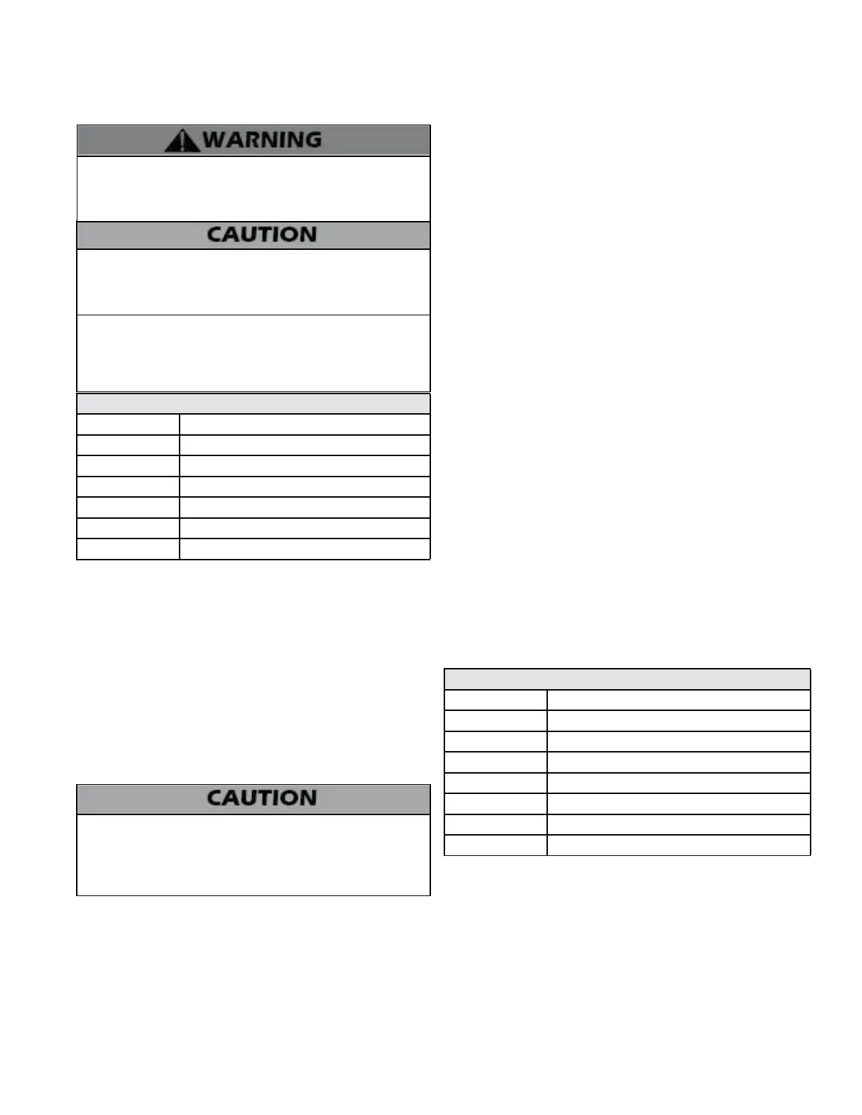
Expansion Tank Sizing
Model Heat Exchanger Volume (Gallons)
55 / 80 2.2
110 2.6
155 6.2
199 6.1
285 6.1
399 7.9
Table 4 - Expansion Tank Sizing
DO NOT install automatic air vents on closed type expansion tank
systems. Air must remain in the system and return to the tank to
provide an air cushion. An automatic air vent would cause air to
leave the system, resulting in improper operation of the expansion
tank.
E. Circulators
Sizing Space Heat System Piping
1. See Applications in this manual. In all diagrams, the space heating
system is isolated from the boiler loop by the primary/secondary
connection.
2. Size the piping and components in the space heating system
using recognized design methods.
DO NOT use the boiler circulator in any location other than
the ones shown in this manual. The boiler circulator location is
selected to ensure adequate ow through the boiler. Failure to
comply with this caution could result in unreliable performance
and nuisance shutdowns from insucient ow.
F. Hydronic Piping with Circulators, Zone Valves, and
Multiple Boilers
This boiler is designed to function in a closed loop hydronic system.
It is recommended to install a temperature and pressure gauge (not
included with the boiler) to allow the user to monitor system pressure
and outlet temperature from the boiler. It is important to note that the
boiler has a minimal amount of pressure drop that must be calculated
when sizing the circulators. Unless the system has a closed type
expansion tank, each boiler installation must have an air elimination
device that will remove air from the system.
Install the boiler so the gas ignition system components are protected
from water (dripping, spraying, etc.) Allow clearance for basic service
of boiler circulator, valves and other components.
Observe the minimum 1” clearance around all uninsulated hot
water pipes when openings around pipes are not protected by non-
combustible materials.
On a boiler installed above radiation level, some states and local codes
require a low water cut o device, which is an optional part available
through HTP (Part # 7600P-104 for 55 – 110 models, 7600P-990 for 155
– 399 models). Check with local codes for additional requirements. If
the boiler supplies hot water to heating coils in air handler units, ow
control valves or other devices must be installed to prevent gravity
circulation of boiler water in the coils during the cooling cycle.
Chilled water medium must be piped in parallel with, and isolated
from, the boiler. Freeze protection for new or existing systems must
use glycol that is specically formulated for this purpose. Antifreeze
must include inhibitors that will prevent the glycol from attacking
the metallic system components. Make certain that the system uid
is checked for the correct glycol concentration and inhibitor level. The
system should be tested at least once a year and as recommended by
the producer of the glycol solution. Allowance should be made for the
expansion of the glycol solution in the system piping. Example: 50%
by volume glycol solution expands 4.8% in volume for a temperature
increase from 32
o
F to 180
o
F, while water expands 3% with the same
temperature rise.
G. Circulator Sizing
Minimum Boiler Flow Rates
Model Minimum Flow (GPM)
55 3.5
80 5.4
110 7
155 9.7
199 12.5
285 17.9
399 25
Table 5 - Minimum Flow Rates
In addition, the heat exchanger has a minimum total water volume
that must be taken into account when sizing the circulator. Minimum
ow rates are listed in the table below.
The heat exchanger has a pressure drop that must be considered in
your system design. Refer to Figure 7 for pressure drop through the
heat exchanger.

 Loading...