LP-387 Rev. 011 Rel. 005 Date 1.3.19
37
NOTE: Check with your local gas company to determine if
combustion condensate disposal is permitted in your area. In the
state of Massachusetts, condensate must be neutralized before
entering a drain.
This boiler is a high eciency appliance, and therefore produces
condensate: a by-product of the combustion process. A condensate
collection system with an internal oat switch monitors condensate
level to prevent it from backing up into the combustion system.
There is a exible line that must be piped to a drain or condensate
pump.
Condensate from the boiler is slightly acidic with a pH of 3.2 - 4.5. To
avoid long term damage to the drainage system and to meet local
code requirements, HTP recommends neutralizing condensate with
a Condensate Neutralizer Kit (Part # 7450P-212 for 55 - 285 models,
Part # 7350P-611 for the 399 model). The neutralizer kit connects to
the drain system and contains limestone chips that neutralize the
pH level of the condensate. The neutralizer kit should be checked
annually and the limestone chips replenished if necessary. When
replacing the limestone chips, take care to ensure chips are no
smaller than ½” to avoid blockage in condensate piping (refer to
Figure 26 for piping of the condensate neutralizer.)
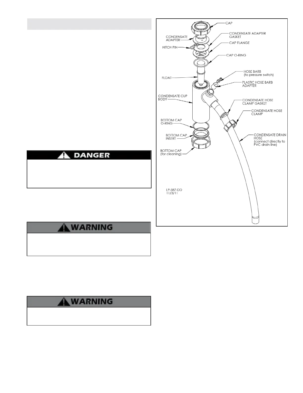
Figure 24 - Condensate Trap Detail
Condensate Trap Installation Instructions
The condensate trap assembly MUST BE PROPERLY INSTALLED
according to these instructions when operating the boiler.
Operating the boiler without the condensate trap assembly will
cause ue gases to leak and result in serious personal injury or
death.
1. Ensure all parts shown in Figure 24, Condensate Detail, are
included with the condensate trap. If any parts are missing, DO NOT
install the trap. Replace the entire condensate assembly.
NOTE: Before installation, clean out the condensate collector with
water to remove any foreign matter that may block the condensate
line.
Do not install the condensate assembly if a component is lost
or missing. Replace the entire assembly. Failure to follow this
warning could result in property damage, serious personal injury,
or death.
2. NOTE: The installer should ll the condensate trap with tap water
prior to assembly on the boiler.
3. Slide the condensate trap adapter onto the drain tube until the
holes line up with the groove.
4. Insert stainless steel lock pin to lock condensate adapter to the
drain tube.
5. Connect the clear hose from the pressure switch to the hose barb.
Do not operate the boiler without the clear hose attached from
the hose barb to the pressure switch. Failure to follow this warning
could result in property damage, serious personal injury, or death.
NOTE: The use of ¾” PVC or CPVC pipe are acceptable materials for
condensate piping. However, use materials approved by the authority
having jurisdiction.
In the absence of other authority, PVC and CPVC pipe must comply with
ASTM D1785 or D2845. Cement must comply with ASTM D2564 for PVC
or ASTM F493 for CPVC. For Canada, use CSA or ULC certied PVC or
CPVC pipe, ttings, and cement. If pipe is used, deburr and chamfer pipe
to allow proper mating to the drainage assembly.
5. Run condensate drain hose to 1” PVC or CPVC drain pipe. See Figure
26.
NOTE: DO NOT cement drain hose to the PVC drainage pipe!
NOTE: To allow for proper drainage on long horizontal runs, a second
line vent may be required and tubing size may need to increase to
1”. Failure to add a second vacuum break could result in condensate
backup, improper boiler operation, and nuisance shutdowns.
NOTE: See Part 14, this manual, for instructions on how to maintain the
condensate trap.
Part 6 - Condensate Removal
 Loading...