LP-387 Rev. 011 Rel. 005 Date 1.3.19
45
B. Check Inlet Gas Pressure
The gas valve is equipped with an inlet gas pressure tap that can be
used to measure the gas pressure to the unit. To check gas pressure,
perform the steps listed below:
1. IMPORTANT! Before you connect to the inlet pressure, shut o
the gas and electrical power to unit.
2. Loosen the pressure tap with a small screwdriver. Refer to Figure
35 for location.
3. Each unit is equipped with a needle valve that will accept a 5/16 ID
hose to connect to a digital manometer or liquid gauge to measure
incoming pressure from 0-35” w.c. See Figure 35.
4. Turn on the gas and power up the unit.
5. Put the unit into manual test mode (details on test mode are in
Part 10). In test mode, monitor pressure to assure it does not drop
below 1 inch from its idle reading. If gas pressure is out of range
or pressure drop is excessive, contact the gas utility, gas supplier,
qualied installer, or service agency to determine correct action that
is needed to provide proper gas pressure to the unit. If Gas Pressure
is within normal range proceed to Step 6.
6. Exit test mode, then turn power o and shut o gas supply at
the manual gas valve before disconnecting the hose from the gas
monitoring device. Tighten screw on the pressure tap and turn gas
on. Check for leaks with soapy solution. Bubbles will appear on the
pipe to indicate a leak is present.
Use two wrenches when tightening gas piping at the boiler: One
to prevent the boiler gas line from turning. Failure to prevent the
boiler gas connection from turning could result in damage to
the gas line components, substantial property damage, severe
personal injury, or death.
CSA or UL listed exible gas connections can be used when
installing the boiler. Flexible gas connections have dierent
capacities and must be sized correctly for the connected boiler
ring rates. Consult with the ex line supplier to assure the line size
is adequate for the job. Follow local codes for proper installation
and service requirements.
Ensure the pressure tap screw is properly tightened to prevent gas
leaks. Failure to do so could cause substantial property damage,
severe personal injury, or death.
DO NOT adjust or attempt to measure gas valve outlet pressure. The
gas valve is factory-set for the correct outlet pressure and requires
no eld adjustment. Attempts by the installer to adjust or measure
the gas valve outlet pressure could result in damage to the valve and
cause substantial property damage, severe personal injury, or death.
Ensure that the high gas pressure regulator is as least 6 – 10 feet
upstream of the appliance. Failure to do so could result in substantial
property damage, severe personal injury, or death.
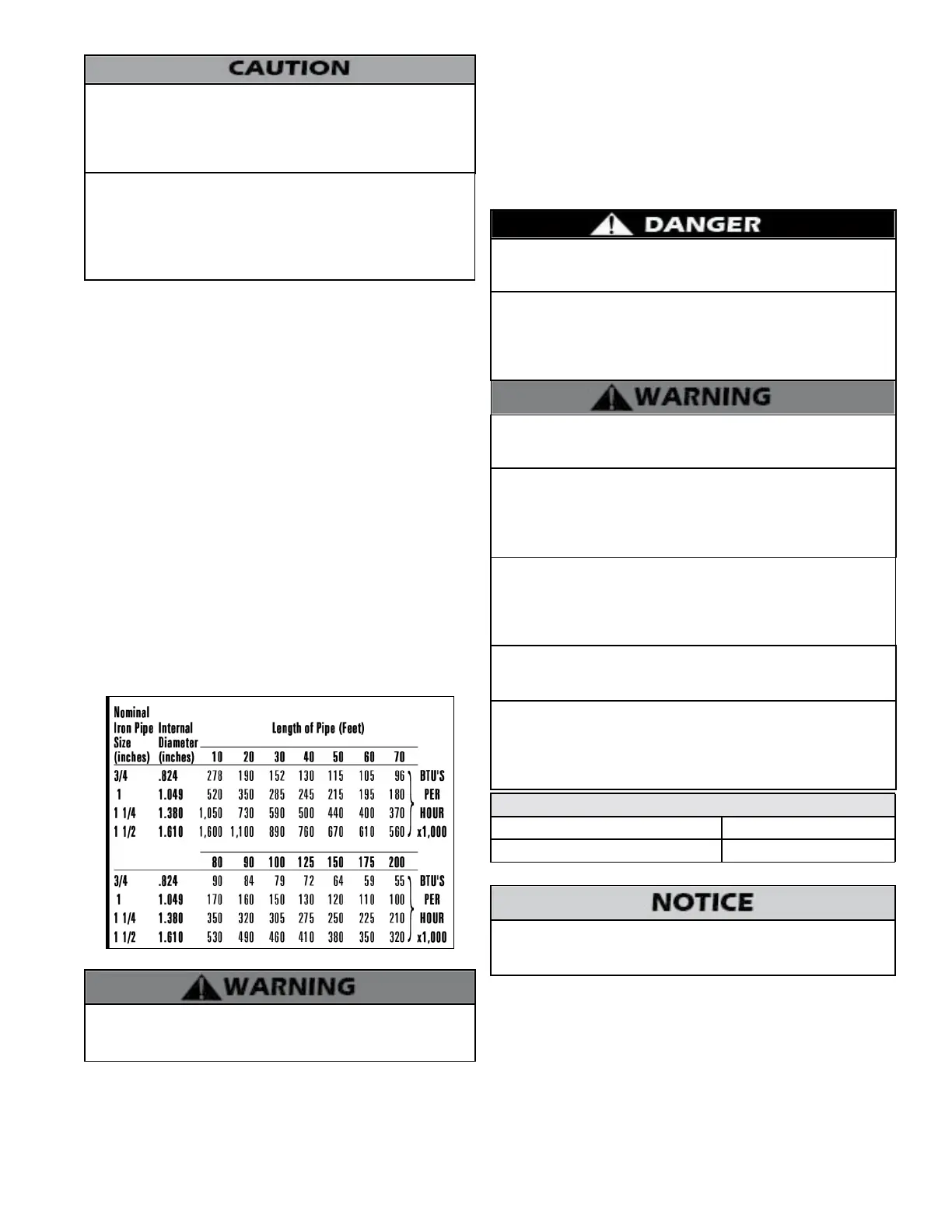
Table 15 - Gas Pipe Sizing / BTU’s per Hour
Do not do a gas conversion on this boiler without an ocially
approved conversion kit and instructions supplied by HTP. Failure to
use a conversion kit when converting the boiler to re on Natural
or Propane gas will result in extremely dangerous burner operation,
leading to re, explosion, severe personal injury, or death.
Strain on the gas valve and ttings may result in vibration, premature
component failure and gas leakage, and result in re, explosion,
property damage, severe personal injury, or death.
Adjustments to the throttle screw or oset may only be made by
a qualied gas technician using a calibrated combustion analyzer
capable of measuring CO2 and CO. Failure to follow this instruction
could result in re, explosion, property damage, severe personal
injury, or death.
Gas conversion should be performed BEFORE the boiler is installed.
Carefully follow the gas conversion instructions when performing
the conversion.
Natural gas at high altitude might contain less heating value than
typical 1,000 BTU/cu ft and therefore can cause improper air / gas
mix leading to improper combustion. For natural gas installations
above 3,000 ft, call your gas provider to determine the heating value
of the supplied natural gas.
The gas piping must be sized for the proper ow and length of
pipe to avoid pressure drop. The gas meter and regulator must be
properly sized for the total gas load. If you experience a pressure
drop greater than 1” w.c. (.87 kPa), the meter, regulator or gas line may
be undersized or in need of service. You can attach a manometer to
the incoming gas drip leg after removing the cap. The gas pressure
must remain between 3.5” (.87 kPa) and 14” (3.5 kPa) during stand-by
(static) mode and while in operating (dynamic) mode.
If an in-line regulator is used, it must be a minimum of 10 feet from the
boiler. It is very important that the gas line is properly purged by the
gas supplier or utility. Failure to properly purge the lines, or improper
line sizing, will result in ignition failure. This problem is especially
noticeable in NEW LP installations and empty tank situations. This
situation can also occur when a utility company shuts o service to an
area to provide maintenance to their lines. This gas valve must not be
replaced with a conventional gas valve under any circumstances.
Natural or LP Gas
Minimum Pressure 3.5” WC
Maximum Pressure 14”WC
Table 16 - Gas Pressure Requirements
Do not re (operate) the boiler until all connections have been
completed and the heat exchanger is lled with water. Doing so will
damage the boiler and void the warranty.

 Loading...