LP-387 Rev. 011 Rel. 005 Date 1.3.19
41
Failure to use the correct sensor may result in tank temperature
being either above or below set point, and could result in decreased
performance, substantial property damage, or heightened risk of
injuries due to scalds.
Caution should be used to ensure neither of these terminals becomes
connected to ground. Failure to do so can result in property damage,
personal injury, or death.
NOTE: If sensor wires are located in an area with sources of potential
electromagnetic interference (EMI), the sensor wires should be
shielded, or the wires routed in a grounded metal conduit. If using
shielded cable, the shielding should be connected to the common
ground of the boiler.
K. Optional UL353 Low Water Cut-
O Interface Kit
If an optional UL 353 Low Water Cut-O
(LWCO) Interface Kit is used, the control
box of the kit should be mounted to the
left side of the boiler cabinet near the low
water cut-o probe, which is located on
the outlet nipple of the boiler.
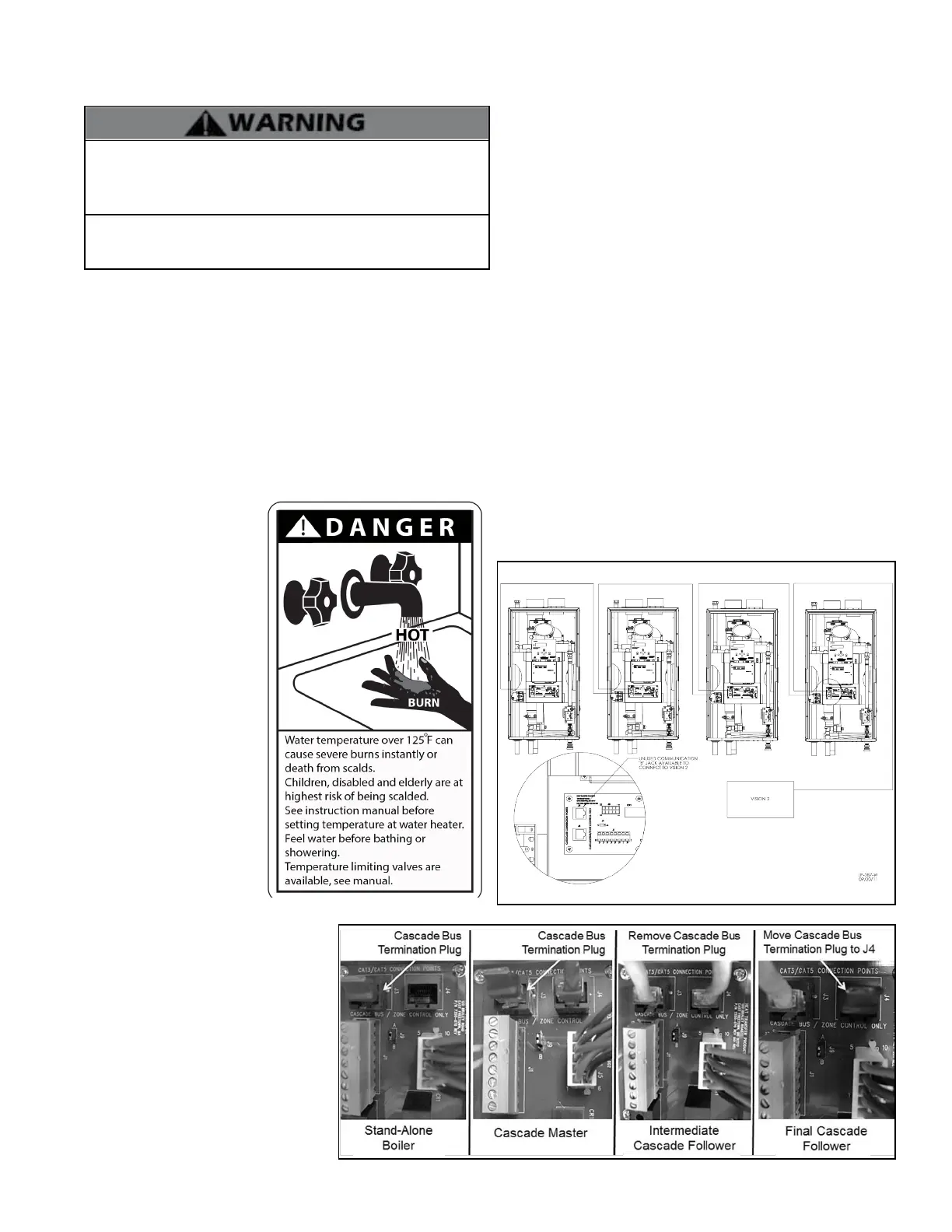
L. Wiring of Cascade System Communication Bus
1. A Cascade Bus Termination Plug has been installed on the
customer connection board of this boiler. The purpose of this plug
is to stabilize communication between multiple boilers and reduce
electrical “noise”. See Figures 30 and 31 for Cascade Bus Termination
Plug installation detail.
2. Use standard CAT3 or CAT5 computer network patch cables to
connect the communication bus between each of the boilers. These
cables are readily available at any oce supply, computer, electronic,
department or discount home supply store in varying lengths. If you
possess the skills you can also construct custom length cables.
3. It is recommended to use the shortest length cable that will
reach between the boilers and create a neat installation. Do not run
unprotected cables across the oor where they may become wet
or damaged. Avoid running communication cables parallel and
close to or against high voltage (120 volt or greater) wiring. HTP
recommends that the maximum length of communication bus
cables not exceed 200 feet.
4. Route the communication cables through one of the knockouts
in the cabinet.
Figure 30 - Wiring Cascade System
Figure 31 - Cascade Termination Plug Detail
J. Optional 0-10 Volt Building Control Signal
1. A signal from a building management system may be connected to
the boiler to enable remote control. This signal should be a 0-10 volt
positive-going DC signal. When this input is enabled using the installer
menu, a building control system can be used to control the set point
temperature of the boiler. The control interprets the 0-10 volt signal as
follows; when the signal is between 0 and 1.5 volts, the boiler will be
in standby mode, not ring. When the signal rises above 1.5 volts, the
boiler will ignite. As the signal
continues to rise towards its
maximum of 10 volts, the
2. Connect the indirect sensor (7250P-325) to the terminals marked
DHW SENSOR (shown in Figures 29 and 32) in the electrical junction
box.
boiler will increase in set
point temperature. See Part
10 for details on the setting of
function 16.
2. Connect a building
management system or other
auxiliary control signal to the
terminals marked 16, 0-10
VOLT + and 17, 0-10 VOLT –
in the electrical junction box
(shown in Figure 29). Caution
should be used to ensure that
the 0-10 VOLT + connection
does not become connected
to ground.
3. Move jumper on connection
board (shown in Figure 31)
from A to B.
4. See Function 17 this manual
to program the 0-10 volt
signal.
NOTE: When a 0-10 volt building management system is installed,
Follow the complete instructions included in the kit for proper
installation.
NOTE: The control system senses system water temperatures
entering and exiting the heat exchanger to provide protection
against low water conditions. Where local codes or jurisdictions
do not accept a pressure device for low water protection, the
jurisdictions may accept these control functions as a means of
providing low water protection.
the return sensor temperature cannot be
monitored through the appliance display.
NOTE: Ensure that the polarity of the
connections from the external modulating
boiler controller to the boiler is correct.
Reversed polarity could lead to erratic and/
or no response from the boiler controller.

 Loading...