LP-387 Rev. 011 Rel. 005 Date 1.3.19
42
5. Connect the boilers in a daisy chain conguration as shown
below. It is best to wire the boilers using the shortest wire runs
rather than trying to wire them in the order that they are addressed.
The communication bus jacks on the customer connection panel
are interchangeable so you can use either one or both in any order
to connect the cable.
If you have connected the boilers to each other properly, there will
be no open communication connection ports.
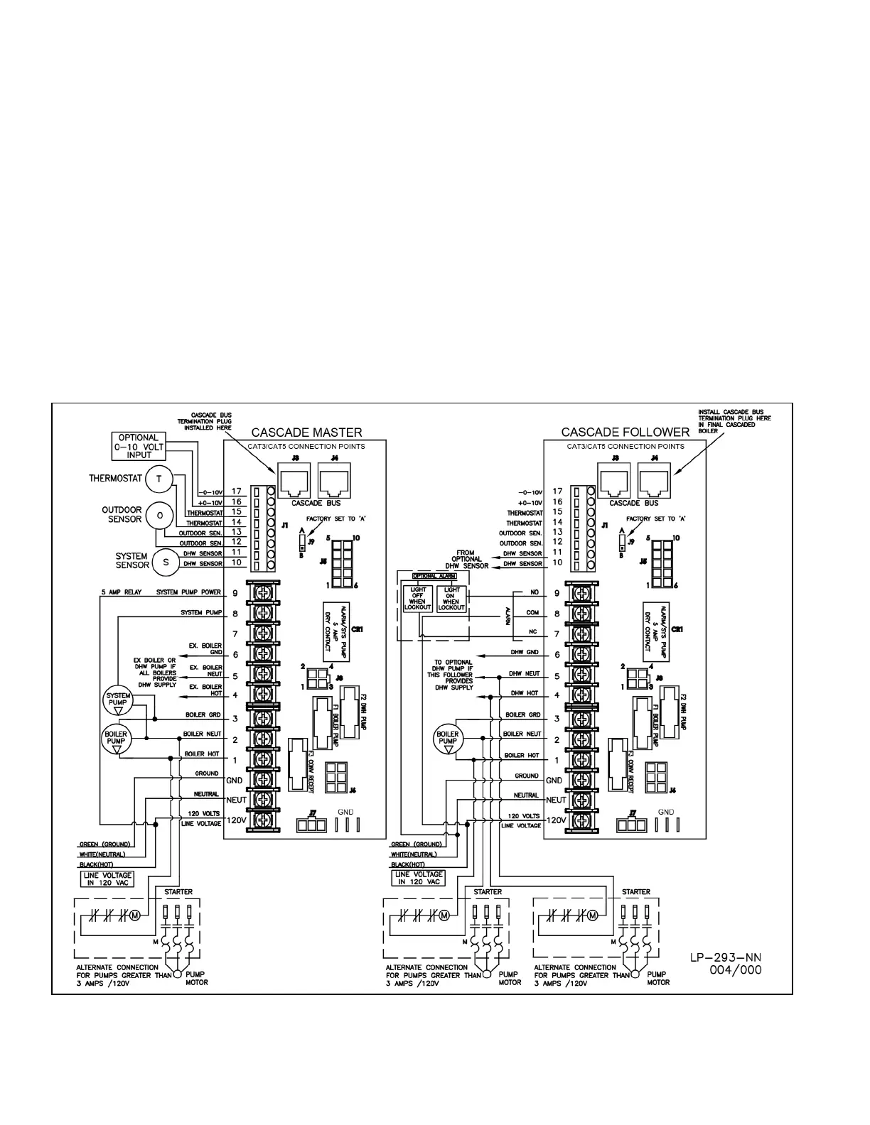
M. Cascade Master Pump and Sensor Wiring
1. Connect the system pump hot wire to the terminal marked 8.
2. Connect the system pump neutral to the 2 terminal and the pump
ground wire to the 3 terminal.
3. Connect a jumper wire from the 120 VOLT terminal to the 9
terminal.
4. Connect the boiler pump to the terminals marked 1 (HOT), 2
(NEUT) and 3 (GND).
5. Connect system pipe sensor to terminals marked 10 and 11.
6. In cascaded systems where the ENTIRE set of boilers provides
DHW supply, connect the DHW pump to the terminals marked 4 -
HOT, 5 - NEUT, 6 - GND on the master boiler.
N. Cascade Follower Pump and Sensor Wiring
1. Connect the boiler pump to the terminals labeled 1 (HOT), 2 (NEUT),
and 3 (GND).
2. In cascaded systems where ONLY ONE boiler provides DHW supply,
connect the DHW pump to the terminals marked 4 - HOT, 5 - NEUT, 6 -
GND on the boiler that will meet DHW demand.
3. An alarm bell or light can be connected to the alarm contacts of the
follower boiler. The normally closed alarm contact may be used to turn
a device o if the boiler goes into lockout mode. The alarm contacts
are rated 5 amps at 120 VAC.
To connect an alarm device, connect the power for the device to
the ALARM COM terminal. Connect the alarm device hot wire to the
ALARM NO terminal. Connect the neutral or return of the alarm device
to the neutral or return of the power for the alarm device.
To connect a device that should be powered o during a boiler lockout
condition, follow the same instructions as above except use the ALARM
NC terminal rather than the ALARM NC terminal.
Note that in a cascade system the alarm output of the boiler addressed
as #1 will also be active if the master boiler has a lockout condition. The
alarm output of boilers addressed as 2-7 will only activate an alarm if a
lockout condition occurs on that specic boiler.
See Figure 32 for Cascade Master and Follower Wiring detail.
Figure 32 - Cascade Master and Follower Wiring

 Loading...