LP-387 Rev. 011 Rel. 005 Date 1.3.19
47
D. Fill and Test Water System
Ensure the boiler is full of water before ring the burner. Failure to do
so will damage the boiler. Such damage IS NOT covered by warranty,
and could result in property damage, severe personal injury, or
death.
1. Fill the system only after ensuring water chemistry meets the
requirements listed in this manual.
2. Close the manual and automatic air vents and boiler drain valve.
3. Fill to the correct system pressure. Correct pressure will vary with
each application.
a. Typical cold water ll pressure for a residential system is 12 psi.
b. Pressure will rise when boiler is turned on and system water
temperature increases. Operating pressure must never exceed the
relief valve pressure setting.
4. At initial ll and during boiler startup and testing, check system
thoroughly for leaks. Repair all leaks before proceeding further.
Eliminate all system leaks. Continual fresh make-up water will reduce
boiler life. Minerals can build up in the heat exchanger, reducing
heat transfer, overheating the heat exchanger and causing heat
exchanger failure.
5. The system may have residual substances that could aect water
chemistry. After the system has been lled and leak tested, verify
that water pH and chloride concentrations are acceptable by sample
testing.
It is important to purge the system of air to avoid damage to the
boiler.
E. Purge Air from Water System
1. Purge air from the system:
a. Connect a hose to the purge valve and route hose to an area where
water can drain and be seen.
b. Close the boiler or system isolation valve between the purge valve
and ll connection to the system.
c. Close zone isolation valves.
d. Open quick-ll valve on cold water make-up line.
e. Open purge valve.
f. Open the isolation valves one zone at a time. Allow water to run
through the zone, pushing out the air. Run water until no noticeable
air ow is present. Close the zone isolation valves and proceed with
the next zone. Follow this procedure until all zones are purged.
g. Close the quick-ll water valve and purge valve and remove the
hose. Open all isolation valves. Watch the system pressure rise to
correct cold-ll pressure. It is recommended that you put the pumps
into manual operation to assist in purging the circuits.
h. Disconnect the wires that are connected to the THERMOSTAT
terminals of the customer connection board. Apply power to the
boiler. The display will show the temperature of the water in the
boiler. Press the v and ENTER keys simultaneously and hold for 1
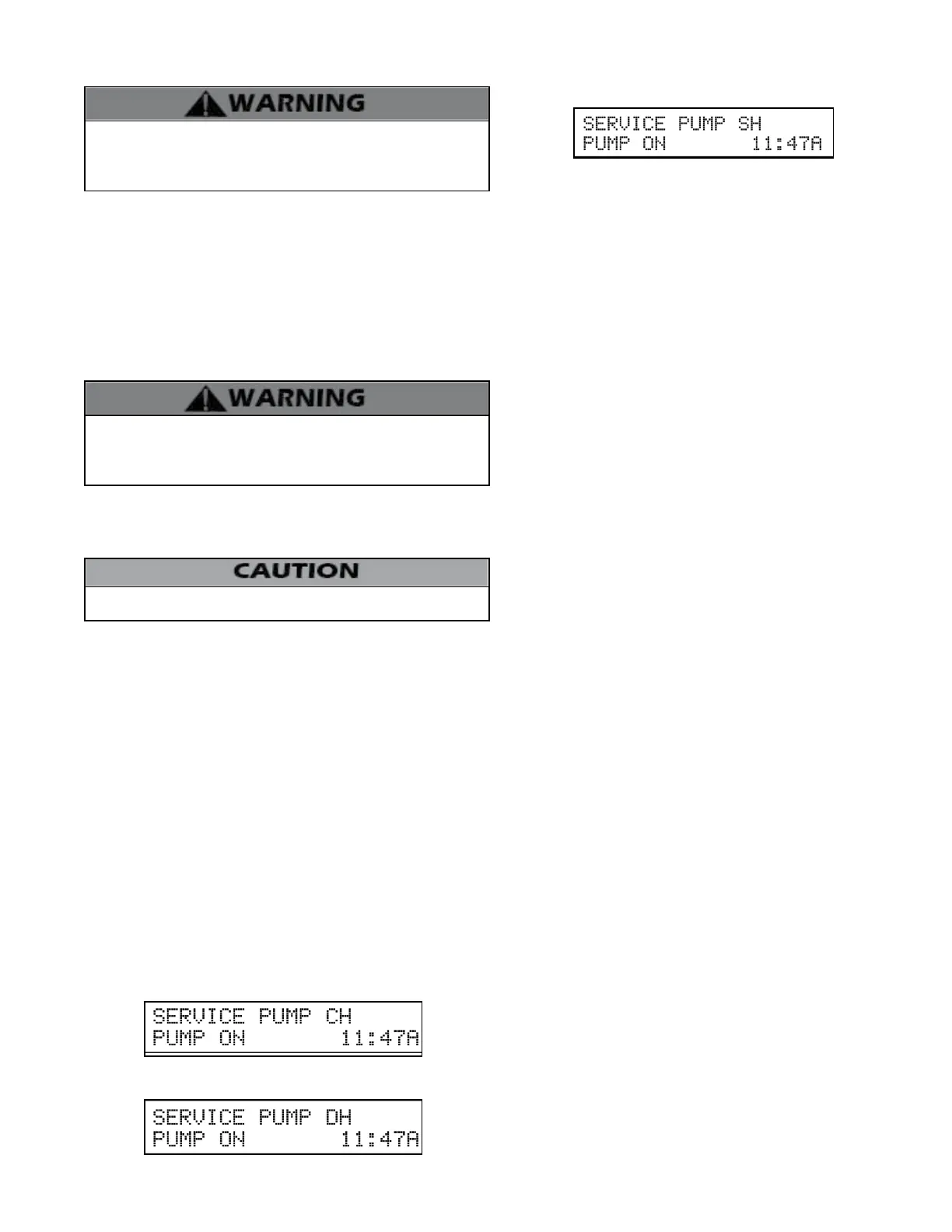
second. The display will read:
The central heating pump will come on. If you then press the ^
key, the central heating pump will shut o. The display will read:
The DHW pump will come on. If the boiler is set up as a cascade
master and you then press the ^ key again, the DHW pump will
shut o. The display will read:
The system pump will come on. Use the ^ and v keys to toggle
between running each pump in the system as required to help
bleed out all entrapped air. Some good indicators that air is
removed include the absence of gurgling noises in the pipes and
pump operation becoming very quiet. Pressing ^ and v together
at any time will return the boiler to normal operation.
i. After the system has operated for ve minutes, eliminate any
residual air by using the manual air vents located throughout the
system.
j. If purge valves are not installed in the system, open manual air
vents in the system one at a time, beginning with the lowest oor.
Close vent when water squirts out. Repeat with remaining vents.
k. Rell to correct pressure.
F. Check Thermostat Circuit(s)
1. Disconnect the two external wires connected to the boiler
thermostat terminals (low voltage terminal strip).
2. Connect a voltmeter across these two incoming wires with power
supplied to the thermostat circuits. Close each thermostat, zone
valve and relay in the external circuit one at a time and check the
voltmeter reading across the incoming wires.
3. There should NEVER be a voltage reading.
4. If a voltage reading does occur under any condition, check and
correct the external wiring. (This is a common problem when using
3-wire zone valves.)
5. Once the external thermostat circuit wiring is checked and
corrected if necessary, reconnect the external thermostat circuit
wires to the boiler low voltage terminal strip. Allow the boiler to
cycle.
G. Condensate Removal
1. The boiler is a high eciency condensing boiler. Therefore, the
unit has a condensate drain. Condensate uid is nothing more than
water vapor, derived from combustion products, similar to that
produced by an automobile when it is initially started.
Condensation is slightly acidic (typically with a pH of 3 to 5) and
must be piped with the correct materials. Never pipe the condensate
using steel, copper, brass or other materials that will be subject to
corrosion. Plastic PVC or CPVC pipe are the only approved materials.
A condensate neutralizer, if required by local authorities, can be
made up of lime crystals, marble or phosphate chips that will
neutralize the condensate. This may be done by the installer or you
may purchase a condensate neutralizer from HTP (7450P-212).
2. The boiler is equipped with a ¾ female socket weld tting
connection that must be piped to a local drain. It is very important
that the condensate line is sloped downward away from the boiler
to a suitable inside drain. If the condensate outlet on the appliance
is lower than the drain, you must use a condensate removal pump,
available from HTP (554200). This pump is equipped with two leads
that can be connected to an alarm or another type of warning device
to alert the user of a condensate overow, which, if not corrected,
could cause property damage.
3. If a long horizontal run is used, it may be necessary to create a vent
in the horizontal run to prevent a vacuum lock in the condensate
line.
4. Do not expose the condensate to freezing temperatures.
5. It is very important you support the condensation line to assure
proper drainage.
H. Final Checks Before Starting Boiler
1. Read Startup Procedures within this manual for proper steps to
start boiler. (See Startup Report to record steps for future reference.)

 Loading...