LP-387 Rev. 011 Rel. 005 Date 1.3.19
7
C. Optional Equipment
Optional equipment available from HTP (and Part #):
• System Sensor (7250P-324)
• 3” PVC Concentric Vent Kit (KGAVT0601CVT)
• 3” Stainless Steel Vent Termination Kit (V1000)
• 4” Stainless Steel Vent Termination Kit (V2000)
• 6” Stainless Steel Vent Termination Kit (V3000)
• 3” Polypro Vent Kit (8400P-001)
• 3” Polypro Pipe
(33’ length # 8400P-002, 49.5’ length # 8400P-003)
• UL 353 Compliant Low Water Cut-O Interface Kit with Manual
Reset (55/80/110 Models - 7600P-104, All other Models -
7600P-990)
• Manual Reset High Limit (7450P-217)
• Alarm System (to monitor any failure) (7350P-602)
• PC Connection Kit (7250P-320)
• Condensate Neutralizer (55 - 285 Models - 7450P-212, 399
Model - 7350P-611)
• Condensate Removal Pump (554200)
• Flow Switch Kit (7450P-213)
NOTE: When using an optional system sensor, pipe insulation must be
wrapped around it to improve temperature measurement accuracy
and increase overall system eciency.
The control can be set to monitor outdoor temperature through
an outdoor sensor to regulate boiler set point. The system can be
further enhanced by installing an indirect water heater to provide
domestic hot water.
The control can regulate the output of multiple boilers through
its cascade system function. The cascade system is capable of
connecting up to eight boilers together in such a way that they
function as one boiler system. This allows for greater turn down
ratios and provides systematic control of the multiple boilers in an
installation to minimize downtime and maximize eciency.
The cascade system works by establishing one boiler as the master
and the other connected boilers as followers. The master boiler
requires a sensor to provide feedback on set point temperature
in order to adjust heating input from the connected boilers. Each
cascaded boiler will have its own pump to provide maximum ow
and control heat exchanger ow rate.
Text Display and Operational LED Light Indicators
The display allows the user to change system parameters and
monitor system outputs.
Gas Valve
Senses suction from the blower, allowing gas to ow only if powered
and combustion air is owing.
All Metal Integrated Venturi
Controls air and gas ow into the burner.
Burner
The high grade stainless steel burner uses premixed air and gas to
provide a wide range of ring rates.
Spark Ignition
The burner is ignited by applying high voltage through the system
spark electrode. The spark from the electrode ignites mixed gas o
of the burner.
Supply Water Temperature Sensor
This sensor monitors the boiler outlet water temperature (System
Supply). The control adjusts boiler ring rate so the supply
temperature will match the boiler set point.
Return Water Temperature Sensor
This sensor monitors boiler return water temperature (System
Return).
Flue Sensor
Monitors ue temperature and adjusts ring rate.
Temperature and Pressure Gauge
Allows the user to monitor system temperature and pressure.
Electrical eld connections with terminal strips
The electrical cover allows easy access to the clearly marked line
voltage and low voltage terminal strips to facilitate wiring the boiler.
Condensate Collection System
This boiler is a high eciency appliance and will produce condensate.
The condensate collection system has a oat switch which monitors
condensate level and prevents condensate from backing up into
the combustion system. Inside the collection system is a built in trap
which seals the combustion system from the connected drain. This
condensate should be neutralized to avoid damage to the drainage
system or piping.
Outdoor Sensor
Monitors outdoor temperature and adjusts unit set point to provide
greater eciency.
0-10 Volt Input
Allows the installer to connect a BMS (Building Management
System) to control the boiler.
Condensate Flue Check System
The check system prevents heat exchanger exhaust from backing
up into the cabinet.
Pump Service Mode
Allows manual operation of pumps to commission system and
check pump operation.
Part 3 - Prepare the Boiler
COLD WEATHER HANDLING - If the boiler has been stored in a very
cold location (BELOW 0
o
F) before installation, handle with care until
the components come to room temperature. Failure to do so could
result in damage to the boiler.
Carefully consider installation when determining boiler location.
Please read the entire manual before attempting installation. Failure
to properly take factors such as boiler venting, piping, condensate
removal, and wiring into account before installation could result in
wasted time, money, and possible property damage and personal
injury.
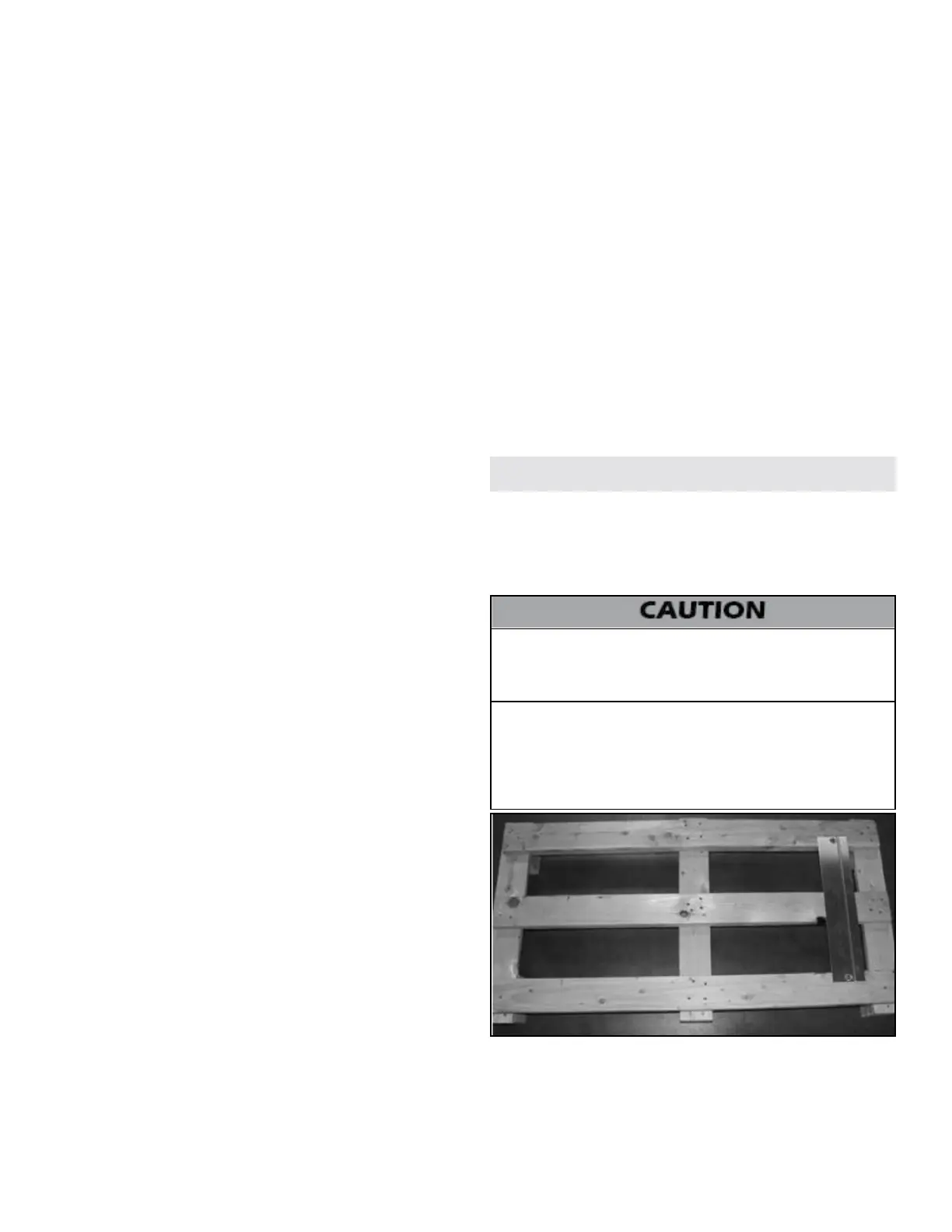
Remove all sides of the shipping crate, and the wooden block that
holds the boiler in place during shipping. Slide the boiler from the
mounting bracket, which is axed to the skid (Figure 1 and 2). Remove
the mounting bracket from the crate (Figure 1). Take care to place the
boiler in a safe location prior to installation to prevent damage to the
mechanical connections.
Figure 1 - Pallet with Axed Mounting Bracket
 Loading...