LP-387 Rev. 011 Rel. 005 Date 1.3.19
40
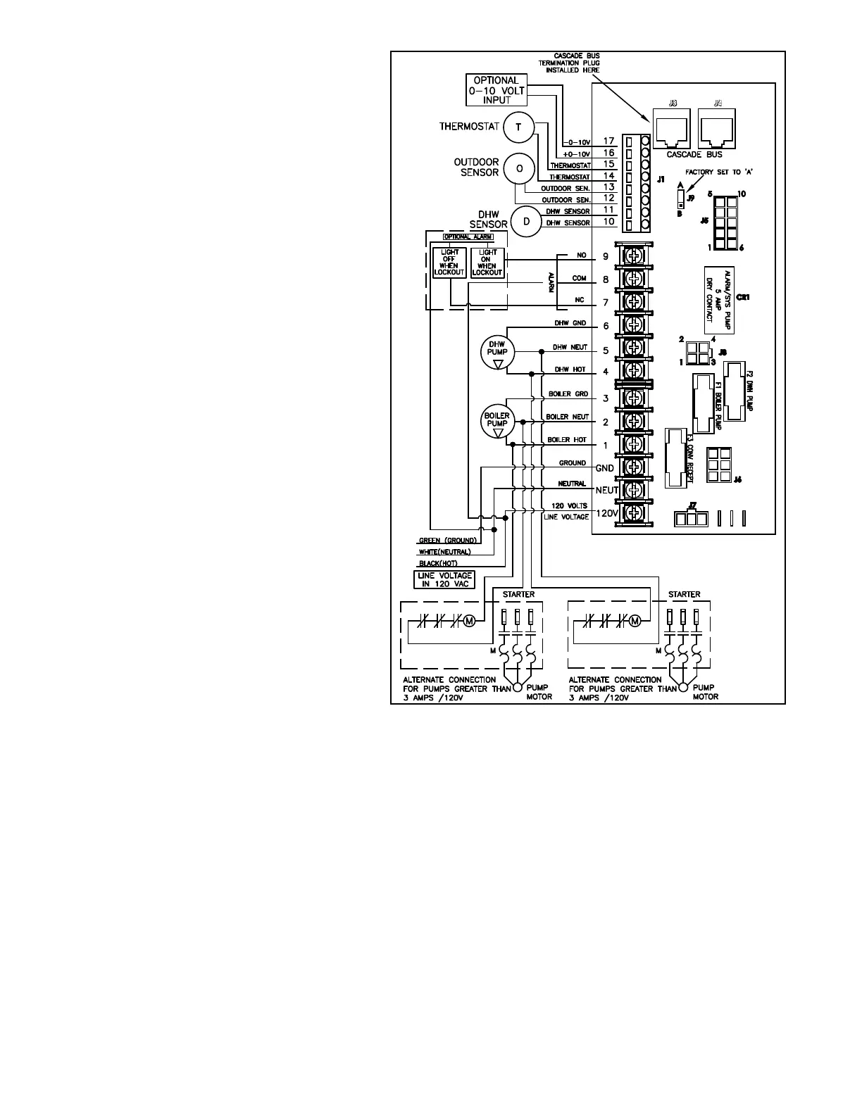
D. Line Voltage Wiring for Standard Boiler
NOTE: A termination plug is included in the CAT 3 / CAT 5 Bus
Connection Point, labeled J3 in Figure 29. DO NOT REMOVE THIS
PLUG! Doing so will aect boiler operation and void warranty.
1. Connect the incoming power wiring to the line voltage
terminal strip in the electrical junction box at terminals 120V,
Neutral, Ground (shown in Figure 29).
2. A line voltage fused disconnect switch may be required,
externally mounted and connected according to local codes that
may apply.
3. Connect the boiler pump as shown in Figure 29 to the terminals
marked 1 – (HOT), 2 – (NEUT), and 3 – (GND). The connections
shown are suitable for a maximum continuous pump draw of 3
amps at 120 volts. If the pump requires more current or voltage
than the 120 volts supplied, an external motor starter or contactor
will be required.
4. Connect the DHW pump to the terminals marked 4 - HOT, 5 -
NEUT, 6 - GND.
E. Alarm Connections
The control includes a dry contact alarm output. This is an SPDT
circuit, rated at 5 amps at 120 volts. This contact can be used to
activate an alarm light or bell or notify a building management
system if the boiler goes into a lockout condition. The circuit
between the ALARM COM and NC terminals is closed during
normal operation and the circuit between ALARM COM and
NO is open during normal operation. The connections depicted
in Figure 29 show two 120 volt lights connected to the alarm
terminals. One light will be on when the boiler is in normal mode
and the other light will be on when the boiler is in lockout mode.
F. Low Voltage Connections for Standard Boiler
1. All low voltage cables should enter the electrical junction box
through the provided knock out holes as shown in Figure 28.
2. Connect all low voltage eld devices to the low voltage
terminal strip located in the electrical junction box.
G. Thermostat
1. Connect the room thermostat to the terminals marked
THERMOSTAT in the electrical junction box (see Figures 29 and 32).
Alternately, any dry contact closure across these terminals will cause
the boiler to run. Take caution to ensure neither of the terminals
becomes connected to ground.
2. Mount the thermostat on an inside wall as central as possible
to the area being heated, but away from drafts or heat producing
devices such as television sets that could inuence the ability of the
thermostat to measure room temperature.
3. If the thermostat is equipped with an anticipator and it is
connected directly to the boiler, the anticipator should be set at
.1 amps. If the thermostat is connected to other device(s), the
anticipator should be set to match the power requirements of the
device(s). See the instruction manual of the connected device(s) for
further information.
If the boiler is congured as a cascade master, the system pump
output is a dry contact output capable of switching 5 amps at
120 volts, in addition to the boiler pump output sourcing 4 amps
each.
The electrical junction box has separate, clearly marked terminal
strips for line voltage and low voltage wiring. Special jacks are
provided for trouble-free cascade system wiring using standard
CAT3 or CAT5 patch cables.
NOTE: If local electrical codes or conditions require an additional
service switch, the installer must provide and install a fused
disconnect or 15 amp (minimum) service switch.
BOILER CONTROL
CAT3/CAT5 CONNECTION POINTS
GND
Figure 29 - Control Wiring
H. Outdoor Sensor
There is no connection required if an outdoor sensor is not used or
the system requires a xed operating temperature.
1. Use a minimum 22 AWG wire for runs of 100 feet or less and minimum
18 AWG wire for runs of up to 150 feet.
2. Mount the outdoor sensor on an exterior surface of the building,
preferably on the north side in an area that will not be aected by
direct sunlight and will be exposed to varying weather conditions.
NOTE: For correct mounting procedures, follow instructions provided
with the sensor.
NOTE: If sensor wires are located in an area with sources of potential
electromagnetic interference (EMI), the sensor wires should be
shielded, or the wires routed in a grounded metal conduit. If using
shielded cable, the shielding should be connected to the common
ground of the boiler.
I. Indirect Sensor
There is no connection required if an indirect water heater is not used
in the installation.
1. The boiler will operate an indirect red water heater with either
a thermostat type aquastat installed in the indirect tank or an HTP
7250P-325 tank sensor. When a tank sensor is used, the boiler control
will automatically detect its presence and a demand for heat from the
indirect water heater will be generated when the tank temperature
falls below the user set point by more than the user selectable oset.
The demand will continue until the sensor measures that the indirect
water heater temperature is above the set point.

 Loading...