17
18
LP-532 REV. 8.13.2014
LP-532 REV. 8.13.2014
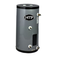
Description/Part #
Main Control Board / 7850P-058
Check Point
(Main PCB)
N/A
Function
This part controls all components contained in the water heater
Failure Event
Abnormalmaincontrolleroperation.
Eects
Whenthemaincontroller hasabnormalcondition,componentsmaynotoperate
properly.
Error Code
Er 38
Diagonostic
Check each connection and/or wires damage on the PCB
Color/WireNumber
N/A
Exhaust temperature Sensor
Water inlet temperature sensor
Heat Exchanger temperature
Water outlet temperature sensor
NO Item Standard
1
Temperature –
Resistance Type
Idling Condition
Temperature(
℃
) Resistance(k
Ω
)
0 ± 0.1
℃
-10.99
25 ± 0.1
℃
-3.906
85 ± 0.1
℃
0.552 ± 3%
Blank is for reference measurement
2
B Fixed Number
(25/85)
3482.4K ± 2%
3
Fixed Number of
Heat dissipation
2.5mW/
℃
(Min.) (While not boiling)
4
Fixed Number of
Heating
8(15)Sec (Max)(63.2% reaching time
while boiling)
5
Range of Workable
Temperature
-4 ~ 230
F
Chapter 2 Components description Chapter 2 Components description
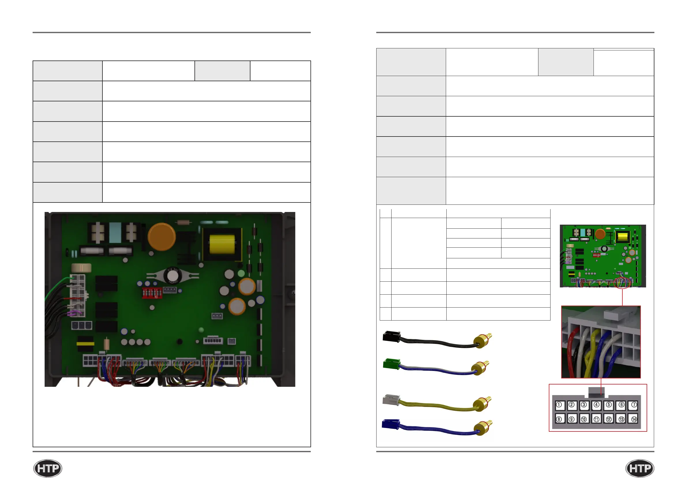
CN7
Description/Part #
HX Temperature Sensor / 7850P-081
ExhaustTemp.Sensor/7850P070
Water Outlet Sensor / 7850P-019
Water Inlet Sensor / 7850P-015
Check Point
(Main PCB)
CN7
Function
The controller compares each sensor with setting temperature then goes to safety
shutdownwhenmeasuredtemperatureisoversettingtemperature.
Failure Event Sensormalfunctionoroverheatingconditionisdetected.
Eects Impropertemperaturemeasurement.
Error Code Er 16, Er 31, Er 33, Er 35
Diagonostic
①Checktemperaturesensorswiringconnection.
②measuresensorresistanceusingamultimeter.
Color/WireNumber
①Exhausttemperaturesensor(white/blue):Connector⑤,⑫
②WaterInlettemperature(blue/blue):Connector④,⑪
③HeatExchangerTemperatureSensor(white/black):Connector②,⑨
④WaterOutletTemperature(yellow/yellow):Connector③,⑩

 Loading...