Trans
missi
on
Mode
Mode
Supp
orted
Application Scenario Legend
UMTS
only
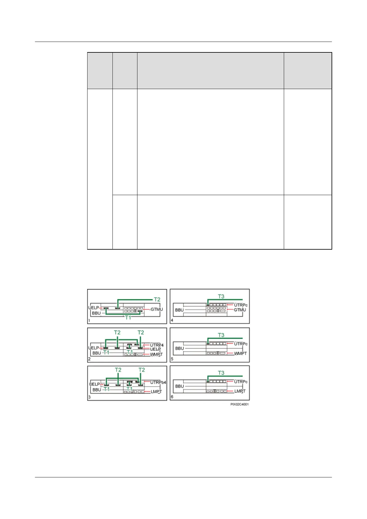
Scenario 1: The UTRPc is configured. The
transmission cable is connected to the FE/GE optical
port or electrical port on the UTRPc.
Scenario 2: The UTRP2 is configured. The
transmission cable is connected to the FE/GE optical
port on the UTRP2.
Scenario 3: The UTRP9 is configured. The
transmission cable is connected to the FE/GE electrical
port on the UTRP9.
Scenario 4: The UTRP is not configured. The
transmission cable is connected to the FE/GE optical
port or electrical port on the WMPT or UMPT.
"5" in the
Figure 7-6
shows the cable
connections in
scenario 1.
LTE
only
Scenario 1: The UTRPc is configured. The
transmission cable is connected to the FE/GE optical
port or electrical port on the UTRPc.
Scenario 2: The UTRP is not configured. The
transmission cable is connected to the FE/GE optical
port or electrical port on the LMPT or UMPT.
"6" in the
Figure 7-6
shows the cable
connections in
scenario 1.
Figure 7-6 Transmission cable connections in a single-mode base station
T1: E1/T1 Surge Protection Transfer Cable
T2: 7.6.1 E1/T1 Cable T3: 7.6.7 FE/GE Fiber Optic Cable
BTS3900C (Ver.C)
Hardware Description 7 BTS3900C Cables
Issue 03 (2013-05-27) Huawei Proprietary and Confidential
Copyright © Huawei Technologies Co., Ltd.
134