FusionModule500 Smart Mini Data Center
Product Description (ECC800e)
Huawei Proprietary and Confidential
Copyright © Huawei Technologies Co., Ltd.
If the positive or negative battery string cable is too thick to be routed through the Hall effect sensor,
or the measurement range of the Hall effect sensor is not enough, use multiple Hall effect sensors to
monitor the current of one battery string. The CIM supports the sum of the monitoring results of
multiple Hall effect sensors, which is set through Multi-Hall cur. setting.
The value of Multi-Hall cur. setting equals the number of positive or negative Hall effect sensors in
a single battery string and should be greater than or equal to 1.
BCB Port
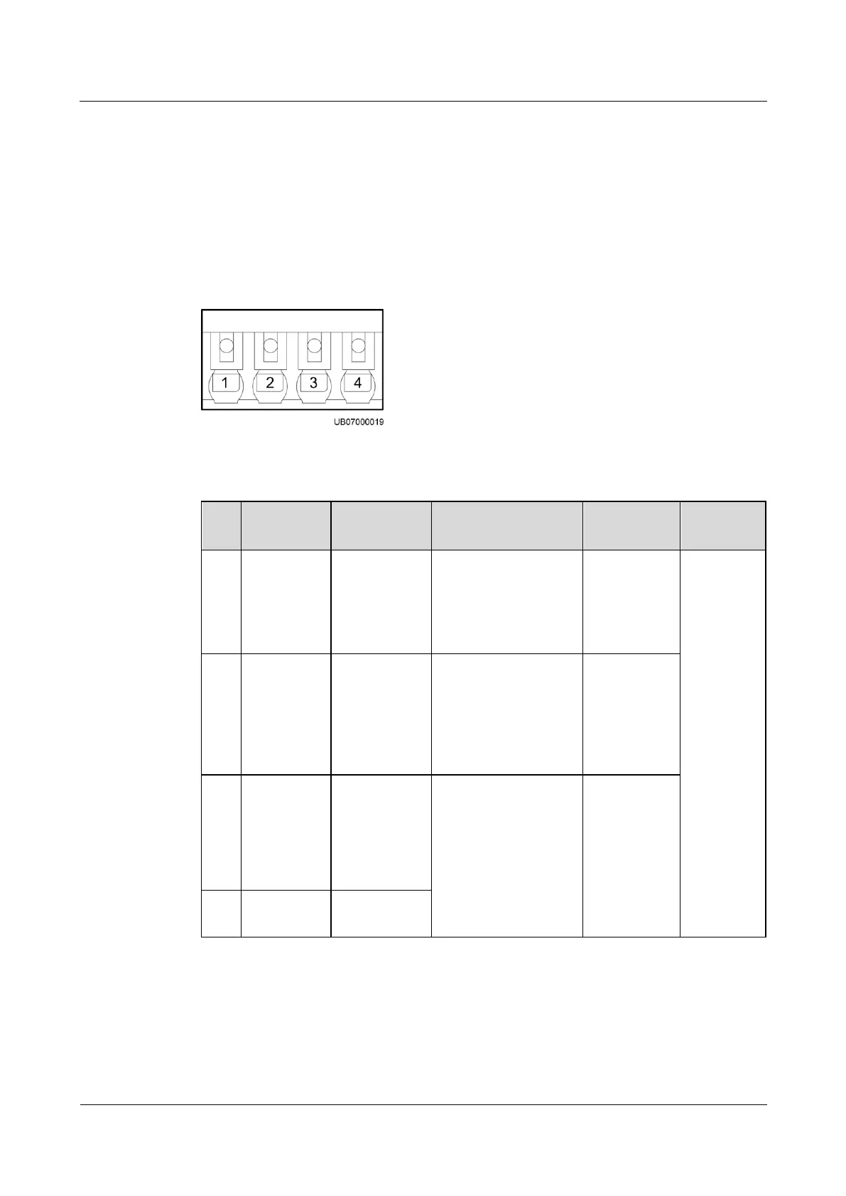
Figure 3-26 BCB port pins
Table 3-34 BCB_1–BCB_4 port pin definitions
Monitors
whether the
BCB box is
connected
Grounded: BCB
connected.
Disconnected:
BCB not
connected.
The four
BCBs can
separately
manage
tripping of
four
battery
routes.
Monitors the
battery circuit
breaker
Grounded: The
battery circuit
breaker is ON.
Disconnected: The
battery circuit
breaker is OFF.
Controls
battery circuit
breaker trip
and delivers
12 V driving
signals
0 V: There is no
driving signal for
BCB tripping.
12 V: There is a
driving signal for
BCB tripping.