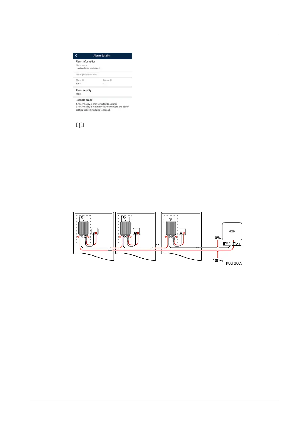
Figure E-1 Alarm details
● The positive and negative terminals of a PV string are connected to the PV+ and PV–
terminals of the solar inverter. The PV– terminal represents a possibility of 0% for the
short-circuit position and the PV+ terminal represents a possibility of 100% for the
short-circuit position. Other percentages indicate that the fault occurs on a PV module
or cable in the PV string.
● Possible fault position = Total number of PV modules in a PV string x Percentage of
possible short-circuit positions. For example, if a PV string consists of 14 PV modules
and the percentage of the possible short-circuit position is 34%, the possible fault
position is 4.76 (14 x 34%), indicating that the fault is located near PV module 4,
including the previous and the next PV modules and the cables of PV module 4. The
solar inverter has a detection precision of ±1 PV module.
Figure E-2 Denition of the percentage of the short-circuit position
Step 4 Set the DC switch to OFF and check whether the connector or DC cable between
the possible faulty PV modules and the corresponding optimizers, or those
between the adjacent PV modules and the corresponding optimizers are damaged.
● If yes, replace the damaged connector or DC cable, set the DC switch to ON,
and view the alarm information.
– If the Low Insulation Resistance alarm is not reported one minute after
the DC is supplied, the inspection on the PV string is complete. Choose
Device Commissioning > Maintenance > Inverter ON/OFF on the App
and send a shutdown command. Set the DC switch to OFF. Go to Step 2
to check other PV strings. Then go to Step 8.
– If the Low Insulation Resistance alarm is still reported one minute after
the DC is supplied, go to Step 5.
● If not, go to Step 5.
Step 5 Set the DC switch to OFF, disconnect the possible faulty PV modules and
corresponding optimizers from the PV string, and connect a DC extension cable
with an MC4 connector to the adjacent PV modules or optimizers. Set the DC
switch to ON and view the alarm information.
SUN2000-(3KTL-10KTL)-M1 Series
User Manual E Locating Insulation Resistance Faults
Issue 17 (2024-01-12) Copyright © Huawei Technologies Co., Ltd. 129
 Loading...