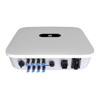
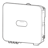
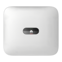
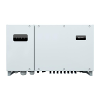
SUN2000-(12KTL, 15KTL, 17KTL, 20KTL)-M0
User Manual
Copyright © Huawei Technologies Co., Ltd.
Figure 6-1 FusionSolar QR code
The screenshots shown in the document are from FusionSolar 2.3.0. Data in the screenshots is for
reference only. The actual screens prevail.
In Britain, only the FusionHome app can be used for commissioning. This document uses the
FusionSolar app as an example to describe the commissioning method. For the FusionHome
app, perform operations as required.
Search for "FusionHome" from the following app stores or scan the corresponding QR code,
download the installation package, and install the FusionHome app by following the
instructions.
Google Play (Android)
App Store (iOS)
Figure 6-2 FusionHome QR code
The initial password for connecting the inverter WiFi is Changeme
Log in to the FusionHome app as installer. The initial password is 00000a.
Use the initial password upon first power-on and change it immediately after login. To ensure
account security, change the password periodically and keep the new password in mind. Not
changing the initial password may cause password disclosure. A password left unchanged for a long
period of time may be stolen or cracked. If a password is lost, devices cannot be accessed. In these
cases, the user is liable for any loss caused to the PV plant.
(Optional) Installer Account Registration
Creating the first installer account will generate a domain named after the company.
 Loading...

