29
Photocell Control with Dimming Functionality Only
The CX Panel also has the ability to control 0-10V dimming loads. The following is a step
by step of how to setup the Photocell programming only. When using the dimming feature
of the CX panel, it is required that the CX is equipped with a CX Dimming Option Card,
(CXDIMCONTRBD), the quantity of cards is based on the Panel(s) being used.
PART 1
Photocell Settings:
• From the Main Menu, select Inputs. Then press the ENTER key.
• Select Input – Scroll to any of the Inputs available based on the CX Panel system.
NOTE: All Inputs that are connected to the system will be present and visible by
continuously scrolling up and down. When highlighted, press the ENTER key or the F1
key to select an Input.
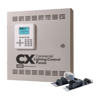
• From the EDIT INPUT Screen, after deciding and editing the Name:, scroll to Type:
and choose, (left or right), <Photocell>.
• Scroll to Settings: [CHANGE], then press the ENTER key.
• Once inside the Settings select the Range: (left or right), 0-100%, 0.3-30ft-c, 3-300ft-c,
and 30-3000ft-c, 50-750ft-c, and 60-6000ft-c, 200-2500ft-c, 1000-7500ft-c, based on
the photosensor’s range conguration.
• After the range is set appropriately scroll to the Sensor lvl:. This value is reective of the Range: setting and is intended
to be the value that the Photo Sensor is “seeing”during programming. Either enter a known value that will be used to
average the calculation to maintain a dimmed FC Level or Scroll down to [SET LEVEL] and press the ENTER button on
the keypad, the value will ll itself based on the light level the photo sensor head is “seeing”at that moment.
• Scroll to Design lvl.: and enter the percentage that the xture is intended to maintain per design intent.
• Scroll down to [SAVE] and press ENTER. This will take you back to the EDIT INPUT screen.
• Next scroll down to [SAVE].
PART2
Dimmer Settings:
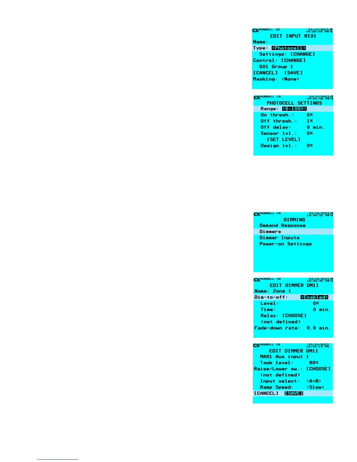
• From the Main Menu, select Dimming, then press the ENTER key.
• Scroll down to Dimmers and press the ENTER key.
• Next scroll down to the Dimmer the Photocell is controlling and press ENTER.
• Once in the Dimmer select and edit the Name:
• Dim-to-off: - (left or right) This feature, when enabled, allows the Relay or Group
selected to turn off when the photocell dims the xtures to a percentage level for a set
amount of time in minutes. If the dim loads are not to turn off due to the photo sensor
level then this section will not be programmed <Disabled>.
• Level: - The percentage, 0-100%, that the Dim-to-off will function. This is a
numerical value entered by the alphanumeric keypad.
• Time: - This is the length of time in minutes that the relay or group selected will
turn Off after the Level: has been maintained. This is a numerical value entered by
the alphanumeric keypad.
• Relay: [CHOOSE] When selected this will show the list of Relays and Groups
available. Simply highlight the Relay or Group and press ENTER.
• Fade-down rate: - This is the time, (in minutes), it takes to dim from 100% to 0% using
daylight harvesting.
• Ramp-up rate: - This is the time, (in minutes), it would take to dim from 0% to 100%
using daylight harvesting.
• Photocell: [CHOOSE] – When this is selected the user will choose the Input that has
the associated photocell that will be used to determine the appropriate dimmed level
for the Dimmer.
• Task level: - This value is a percentage value at Task, (work plane), that will determine
the calculation to maintain the dimmed level of the Dimmer.
• Scroll to [SAVE] and press the ENTER key.
Notes:
1. If additional control devices are to be used to work in conjunction with the Photo Sensor than additional programming will be required.
2. If a Group of relays are to be controlled with the same settings, a single Dimmer and photo sensor may be able to control the entire
Group as long as the dimming channel and relay amperage do not exceed the specications of the CX panel and dimming card.
 Loading...