4
Relay Model
Relay Type
2N 20A, 1P, NO Elect Held, 120/277VAC, 14KAIC Rated
3L 30A, 1P, Latching, 120/277/347VAC, 18KAIC Rated
TN 20A, 2P, NO Elect Held, 208/240/480VAC, 14KAIC Rated
TC 20A, 2P, NC Elect Held, 208/240/480VAC, 14KAIC Rated
Panels are available fully populated with a single relay type or with SP option (Space Only) to allow for eld installation of
individual relays. This is the methodology to provide for panels with a mix of more than one type of relay. Relays can be
ordered separately as follows:
Enclosure Mounting
Typically the CX Panel is installed near the circuit breaker panel or in the ceiling of the room containing the lighting circuits
to be controlled. Select an appropriate location that meets the environmental conditions listed in the specication section of
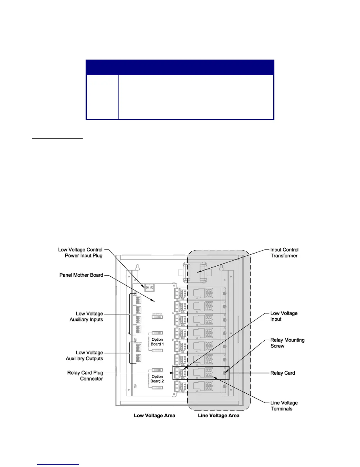
this document. The panel interior is divided into high voltage and low voltage areas as shown in Figures 1(a) (b). Select an
appropriate location for incoming line voltage panel power, branch circuits to be controlled and low voltage input wiring. The
housing is supplied with conduit knock-outs labeled to indicate line or low voltage wiring use. All terminations within the panel
enclosure require installation by a licensed electrician in accordance with national and/or local Electrical Codes.
Figure 1(a) – CX4 or 8 Panel Interior
 Loading...